Procedure for Making the Itty Bitty Radio Telescope
The "Itty Bitty Telescope" was fashioned after the Little Bitty
Telescope described at http://www.setileague.org/articles/lbt.pdf. This website also provides some experiments that can be performed on the "Little Bitty Telescope."
Equipment Needed:
- 1 - DirectTV 18-inch satellite dish with LNB and mounts
- 1 - Channel Master 1004IF
Materials Needed:
From builder supply store:
- 30" x 30" 3/4" composite board or similar material for base
- lazy Susan
- 8 -1 1/4" sheet metal or wood screws
- wood glue or Elmer's glue
- Teflon or nylon washers
- electrical tape
- compass
From Radio Shack
- Terminating resistors, number is dependent on number of LNB on the satellite system. For this dish, 3 were required.
- 4' coax cable
-
2' coax cable
-
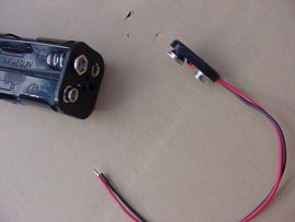
1 - 8 AA battery holder
-
1 - 9-volt battery clip
-
1 - 0.1 MHz RF Choke
-
8 AA batteries
Tools Needed:
- Table saw
- Straight edge
-
7/16 socket wrench
-
Screw drivers, both Phillips and straight
-
Soldering gun, solder, flux
-
Wire cutters
-
Wire striper or knife
-
Drill motor
-
Bits of varying sizes
-
Measuring tape
-
Hack saw
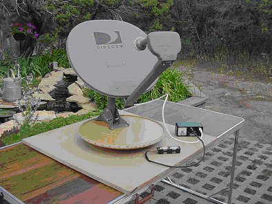
Making the Base for the Itty Bitty Telescope
The satellite dish should come with a mounting bracket used to attach the dish to a house. You will need to attach this bracket to a base that can turn. This makes pointing the dish easier. The base will need to be substantial so as to prevent the dish from toppling over.
- Cut the composite board to 30" by 30".
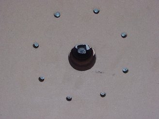
- Attach the bottom of the Lazy Suzanne to the center of the composite board. The base was attached by first drilling holes through the plywood into the base of the Lazy Susan. These holes will need to be counter sunk so that the screw heads will not extend beyond the base. Then the base was glued onto the base, which held the base in place while screws were also screwed from the bottom of the base into the bottom of the base of the Lazy Susan.
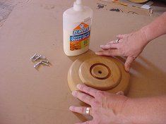
- Attach the top of the Lazy Susan to the base of the Lazy Susan.
Pre-drill a hole through the base board and then use a bolt and washer
to attach the top of the Lazy Susan. This allows for tightening of
the Lazy Susan as needed. (Notice the 8 screws that are counter sunk
that attach the base of the Lasy Susan to the baseboard.)
- Paint or stain the base if desired.
Procedure for assembling the dish
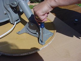
- Your satellite dish should come with the following items: the multi-satellite dish reflector, a mounting bracket used to attach the dish to the house, an arm that attaches the LNB to the dish and the LNB receiver, plus various screws and washers.
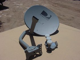
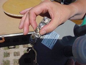
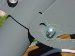
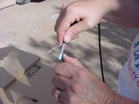
- You will need to install the terminating resistors on all but one of the LNB outputs. For this dish there were 4 LNB outputs, thus requiring 3 terminating resistors. These will help reduce signal loss.
- Insert the 4' coax cable through the LNB arm before attaching it to the LNB.
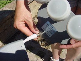
- Attach the LNB to the LNB Arm.
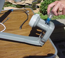
- To reduce the height of the dish, the mounting bracket was shortened. The mast was cut off just below where it started to curve, about 11" from the base. Only the lower portion will be used.

- Attach the lower portion of the mast to the mounting bracket. Use Teflon washers or nylon washers to help make the mast and the dish glide against each other easily.
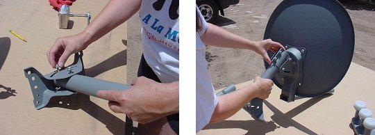
- Attach the mounting bracket to the top of the Lazy Susan.
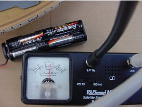
Procedure for assembling the power supply
You will need 12 volts of DC power to operate the Channel Master meter. Eight AA will provide the power through a battery holder and 9-volt connector.
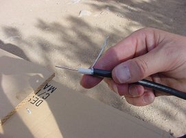
- Cut off the end of the 2' coax cable.
- Strip off about 2" of the black covering. Be careful not the cut through the silver wire shielding.
- Comb and pigtail the silver wire braid shielding. Remove the foil shield, exposing the white insulation.
- Be careful not to score the white insulation. Cut off about 1" of the white insulation, exposing the copper wire.
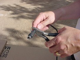
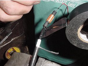
- Solder the RF Choke to the coax center wire.
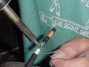
- Solder the other end of the RF choke to the red lead of the 9-volt battery connector.
- Using electrical tape, wrap from the insulation of the coax to the RH choke.
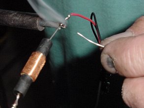
- Solder the silver shielding of the coax cable to the black, or ground, wire of the 9-volt connector.
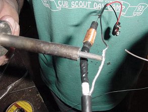
- Using electrical tape, wrap from the insulation of the coax cable to the red and black leads of the 9-volt connector.
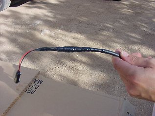
- Insert 8 AA batteries into the battery clip. Attach the battery clip to the 9-volt connector.

- Attach the coax from the LNB to the LNB terminal on the Channel Master.
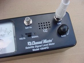
- Attach the coax from the battery pack to the SAT Rx terminal on the Channel Master.
- Congratulations! You have just built an "Itty Bitty Radio Telescope."