![\begin{displaymath}
\Delta S = {{4 \ \sqrt{2} \ k \ T_{sys}} \over
{\gamma \, ...
...n_p [N (N-1) / 2] \Delta\nu \Delta t}}}
\quad {\rm W/m^2/Hz},
\end{displaymath}](img2.gif) |
(1) |
This memo presents a calculation of the sensitivity of the ALMA array, given new thinking on number of antennas, resolutions of different configurations, and other considerations. Much of it is drawn from a similar calculation in Butler et al. (1999), which was patterned after Brown (1998). Numbers for the Supra-THz windows and baselines longer than 10 km are also presented and discussed.
When making an image from interferometric array data, the flux density
sensitivity, or rms noise in flux density units, can be written:
|
(1) |
 |
(2) |
| (3) |
| Frequency (GHz) | Wavelength ( |
|
| 35 | 8600 | 0.80 |
| 110 | 2700 | 0.79 |
| 230 | 1300 | 0.75 |
| 345 | 870 | 0.70 |
| 409 | 650 | 0.63 |
| 675 | 440 | 0.48 |
| 850 | 350 | 0.36 |
| 1020 | 290 | 0.25 |
| 1350 | 220 | 0.10 |
| 1500 | 200 | 0.07 |
Refer Tsys to a point outside the terrestial atmosphere and
compute it as:
| (4) |
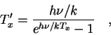 |
(5) |
Assume that
Tsbr = Tamb where Tamb is the ambient
surface temperature. Assume further that
![]() (Bevis et al. 1992), which has been verified to be a fairly
accurate representation of the effective atmospheric temperature by
comparison to detailed atmospheric emission models. Assume
Tamb = 269 K, the average surface temperature at the ALMA site.
(Bevis et al. 1992), which has been verified to be a fairly
accurate representation of the effective atmospheric temperature by
comparison to detailed atmospheric emission models. Assume
Tamb = 269 K, the average surface temperature at the ALMA site.
The ALMA receivers are image separating receivers (SSB) with the
unwanted sideband terminated at 4 K. The noise temperature of these
receivers can be written:
| (6) |
| Frequency (GHz) | |
|
|
|
Tsys (K) | ||
| 35+ | 0.016 | 8.4 | 5.1 | 13.7 | 29 | ||
| 110+ | 0.049 | 18.5 | 16.5 | 14.2 | 50 | ||
| 230+ | 0.078 | 35.3 | 26.1 | 14.6 | 76 | ||
| 345+ | 0.276 | 65.6 | 105 | 18.7 | 190 | ||
| 409+ | 0.544 | 110 | 250 | 26.3 | 380 | ||
| 675+ | 1.789 | 1200 | 2200 | 129.5 | 3500 | ||
| 850+ | 1.601 | 2500 | 1600 | 99.9 | 4200 | ||
| 675* | 0.456 | 210 | 190 | 22.9 | 430 | ||
| 850* | 0.437 | 550 | 180 | 22.0 | 750 | ||
| 1020* | 1.876 | 8200 | 2400 | 140.5 | 10700 | ||
| 1350* | 1.741 | 12200 | 1900 | 114.4 | 14200 | ||
| 1500* | 1.713 | 16400 | 1800 | 108.8 | 18300 | ||
For the second two terms we adopt the ALMA antenna goal of
![]() ,
i.e., 95% of the received power comes from the
forward direction. We will compute Tsys at an airmass of 1.3
(50
,
i.e., 95% of the received power comes from the
forward direction. We will compute Tsys at an airmass of 1.3
(50![]() elevation) and use for the frequency dependent optical
depths on the Chajnantor site the opacities produced by a model
atmosphere for that site. These model opacities are taken from the
Liebe model (Liebe 1989) for frequencies < 1000 GHz, and from the
Traub & Stier model (as implemented by Grossman's AT - but see Traub
& Stier [1976] for a description of the model) for the higher
frequencies. For the frequencies < 1000 GHz, the nominal model
contains 1.5 mm of precipitable water vapor (PWV), which is roughly the
median at the site over all hours and seasons. The supra-THz windows
are entirely opaque at this PWV, so a model atmosphere with less PWV is
used to investigate those frequency windows. The PWV selected is
0.35 mm. The values for the 675 and 850 GHz windows are also
calculated for this PWV, for comparison. This value of PWV (0.35 mm)
is achieved under good conditions at the site, but not the best
conditions. As an illustration, the median PWV in August 1999 was
0.4 mm (personal communication, A. Otarola), and over the 4.5 years of
site testing data, the 225 GHz tipper results indicate that conditions
are this good about 5% of the time. The opacities (and ratios)
produced by this model agree well with those measured with FTS devices
at or near the ALMA site (Matsuo et al. 1998; Matsushita et al.
(1999); Paine & Blundell 1999).
elevation) and use for the frequency dependent optical
depths on the Chajnantor site the opacities produced by a model
atmosphere for that site. These model opacities are taken from the
Liebe model (Liebe 1989) for frequencies < 1000 GHz, and from the
Traub & Stier model (as implemented by Grossman's AT - but see Traub
& Stier [1976] for a description of the model) for the higher
frequencies. For the frequencies < 1000 GHz, the nominal model
contains 1.5 mm of precipitable water vapor (PWV), which is roughly the
median at the site over all hours and seasons. The supra-THz windows
are entirely opaque at this PWV, so a model atmosphere with less PWV is
used to investigate those frequency windows. The PWV selected is
0.35 mm. The values for the 675 and 850 GHz windows are also
calculated for this PWV, for comparison. This value of PWV (0.35 mm)
is achieved under good conditions at the site, but not the best
conditions. As an illustration, the median PWV in August 1999 was
0.4 mm (personal communication, A. Otarola), and over the 4.5 years of
site testing data, the 225 GHz tipper results indicate that conditions
are this good about 5% of the time. The opacities (and ratios)
produced by this model agree well with those measured with FTS devices
at or near the ALMA site (Matsuo et al. 1998; Matsushita et al.
(1999); Paine & Blundell 1999).
The terms in the Tsys equation above, along with the resultant Tsys are shown in Table 2. These numbers agree relatively well with those of Jewell and Mangum (1997), Brown (1998), and Butler et al. (1999) when a common set of assumptions is used.
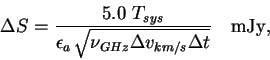
The continuum bandwidth for ALMA is 8 GHz per polarization, so assign
![]() GHz. Using the system temperatures in
Table 2, the aperture efficiencies in
Table 1, and an integration time of 1 minute, the
sensitivities shown in Table 3 are derived.
GHz. Using the system temperatures in
Table 2, the aperture efficiencies in
Table 1, and an integration time of 1 minute, the
sensitivities shown in Table 3 are derived.
| Frequency (GHz) |
|
| 35+ | 0.015 |
| 110+ | 0.026 |
| 230+ | 0.042 |
| 345+ | 0.11 |
| 409+ | 0.24 |
| 675+ | 3.0 |
| 850+ | 4.8 |
| 675* | 0.36 |
| 850* | 0.85 |
| 1020* | 17 |
| 1350* | 54 |
| 1500* | 110 |
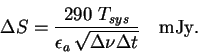
For spectroscopic observations we use a velocity channel width
![]() and write
and write
![]() ,
leaving:
,
leaving:
 |
(7) |
| Frequency (GHz) |
|
| 35+ | 3.9 |
| 110+ | 3.9 |
| 230+ | 4.3 |
| 345+ | 9.3 |
| 409+ | 18 |
| 675+ | 180 |
| 850+ | 260 |
| 675* | 22 |
| 850* | 45 |
| 1020* | 840 |
| 1350* | 2300 |
| 1500* | 4500 |
Consider an observation of a source which fills the synthesized beam,
and assume that the source intensity is large enough that it is in
the Rayleigh-Jeans portion of the spectrum (so that no Planck
correction is necessary). In this case, the brightness temperature
sensitivity is given by:
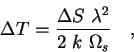 |
(8) |
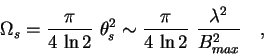 |
(9) |
| (10) |
| Bmax = 0.2 km | 0.4 km | 1 km | 3 km | 10 km | 20 km | |||||||
| frequency |
|
|
|
|
|
|
|
|
|
|
|
|
| (GHz) | (K) | (K) | (K) | (K) | (K) | (K) | (K) | (K) | (K) | (K) | (K) | (K) |
| 35+ | 0.0002 | 0.050 | 0.0008 | 0.20 | 0.0048 | 1.3 | 0.043 | 11 | 0.48 | 130 | 1.9 | 500 |
| 110+ | 0.0003 | 0.049 | 0.0013 | 0.20 | 0.0084 | 1.2 | 0.075 | 11 | 0.84 | 120 | 3.3 | 490 |
| 230+ | 0.0005 | 0.054 | 0.0021 | 0.22 | 0.013 | 1.4 | 0.12 | 12 | 1.3 | 140 | 5.3 | 540 |
| 345+ | 0.0014 | 0.12 | 0.0057 | 0.48 | 0.036 | 3.0 | 0.32 | 27 | 3.6 | 300 | 14 | 1200 |
| 409+ | 0.0030 | 0.23 | 0.012 | 0.93 | 0.076 | 5.8 | 0.68 | 52 | 7.6 | 580 | 30 | 2300 |
| 675+ | 0.038 | 2.3 | 0.15 | 9.1 | 0.96 | 57 | 8.6 | 510 | 96 | 5700 | 380 | 23000 |
| 850+ | 0.062 | 3.3 | 0.25 | 13 | 1.5 | 82 | 14 | 740 | 150 | 8200 | 610 | 33000 |
| 675* | 0.0046 | 0.28 | 0.019 | 1.1 | 0.12 | 6.9 | 1.0 | 62 | 12 | 690 | 46 | 2800 |
| 850* | 0.011 | 0.58 | 0.044 | 2.3 | 0.27 | 14 | 2.5 | 130 | 27 | 1400 | 110 | 5800 |
| 1020* | 0.22 | 11 | 0.89 | 43 | 5.5 | 270 | 50 | 2400 | 550 | 27000 | 2200 | 110000 |
| 1350* | 0.69 | 29 | 2.8 | 120 | 17 | 730 | 160 | 6600 | 1700 | 73000 | 7000 | 300000 |
| 1500* | 1.4 | 57 | 5.7 | 230 | 36 | 1400 | 320 | 13000 | 3600 | 140000 | 14000 | 570000 |
It seems clear from the above sensitivities that we should attempt,
if possible, to put receivers in the 1020, 1350, and 1500 GHz windows
on the ALMA antennas. There is no other instrument in existence, or
currently being planned at an advanced stage, which comes close to the
sensitivities shown above. Given the amount of time that this good
sensitivity can be obtained at the ALMA site, it seems short-sighted to
not include receivers in these windows. If it turns out to be
relatively simple and inexpensive to include the ability to add in
receivers for these windows later in the project (e.g., by explicitly
allowing space in the dewar), then we should certainly do so. Note in
addition that if the actual delivered antennas have a surface accuracy
which meets the design goal (20 ![]() m) rather than the specification (25
m) rather than the specification (25
![]() m), then the efficiencies get better by about a factor of two,
implying a similar improvement in sensitivity. If all of the antennas
do not perform well at the higher frequencies, we might consider
equipping only a subset of the best antennas with receivers in these
windows. One obvious drawback is the very small field of view of our
12 meter diameter antennas at these high frequencies. A possible
solution to this is utilization of an array of smaller antennas to
observe above 1 THz. This would alleviate the short-spacing problem
at the lower frequencies as well.
m), then the efficiencies get better by about a factor of two,
implying a similar improvement in sensitivity. If all of the antennas
do not perform well at the higher frequencies, we might consider
equipping only a subset of the best antennas with receivers in these
windows. One obvious drawback is the very small field of view of our
12 meter diameter antennas at these high frequencies. A possible
solution to this is utilization of an array of smaller antennas to
observe above 1 THz. This would alleviate the short-spacing problem
at the lower frequencies as well.
It also seems clear from the brightness sensitivity shown above that
going to 20 km baselines is not as silly an idea as it once seemed.
The brightness sensitivity reached (
![]() K in 1
minute for
K in 1
minute for
![]() mm) is a useful one for investigating
phenomena at very high resolution (note that the resolution of a 20 km
array at 345 GHz is
mm) is a useful one for investigating
phenomena at very high resolution (note that the resolution of a 20 km
array at 345 GHz is ![]() 10 masec!). Here, in contrast to the case
for the Supra-THz window receivers, there are some more serious
technological, engineering, and cost issues. In addition, preliminary
studies by Lee Mundy and collaborators indicate that even in the 10 km
array the sampling of the UV-plane is poor, resulting in noticably
poorer imaging performance than is achieved with the 3 km array. This
needs to be more fully understood (e.g., can we design a 20 km array
that, when supplemented with data from the 10 and 3 km arrays gives
good UV-coverage?). It is also not clear that we could fit a 20 km
array on the site, given current topography and geopolitical
constraints. A detailed analysis of these issues should be completed
before a strong recommendation to have these longer baselines is issued.
10 masec!). Here, in contrast to the case
for the Supra-THz window receivers, there are some more serious
technological, engineering, and cost issues. In addition, preliminary
studies by Lee Mundy and collaborators indicate that even in the 10 km
array the sampling of the UV-plane is poor, resulting in noticably
poorer imaging performance than is achieved with the 3 km array. This
needs to be more fully understood (e.g., can we design a 20 km array
that, when supplemented with data from the 10 and 3 km arrays gives
good UV-coverage?). It is also not clear that we could fit a 20 km
array on the site, given current topography and geopolitical
constraints. A detailed analysis of these issues should be completed
before a strong recommendation to have these longer baselines is issued.
We note two considerations concerning the numbers presented above. First, we have assumed here that we have an almost perfect instrument, i.e., there is no extra phase fluctuation from electronics (other than thermal noise), atmosphere, pointing errors, etc... In particular, for the continuum sensitivity, we have assumed that the 1/f noise of the receivers does not dominate the thermal noise. This is the current specification for that quantity, and places a strong constraint on the 1/f noise of the receivers, as has been recognized. Secondly, the numbers presented here are only really valid for unresolved or partially resolved sources. For complex resolved sources (perhaps a large fraction of sources which will be observed by ALMA), it is not the strict sensitivity that is important, but rather the imaging fidelity which will determine the quality of many of the measurements/images. Simulations are indicating that the achievable fidelity might not be better than a few percent (Holdaway 1997; Wright 1999). Work continues on means of improving image fidelity to match the unparalleled raw sensitivity of the instrument.
Brown, R.L., Technical specification of the Millimeter Array, Proc. SPIE, 3357, 231-441, 1998
Butler, B., R. Brown, L. Blitz, J. Welch, J. Carlstrom, D. Woody, & E. Churchwell, Report of the Antenna Size Committee Meeting, MMA Memo. No. 243, 1999
Holdaway, M.A., Effects of Pointing Errors on Mosaic Images with 8m, 12m, and 15m Dishes, MMA Memo. No. 178, 1997
Jewell, P.R., & J.G. Mangum, System Temperatures, Single Versus Double Sideband Operation, and Optimum Receiver Performance, MMA Memo. No. 170, 1997
Kerr, A.R., M.J. Feldman, & S.-K. Pan, Receiver Noise Temperature, the Quantum Noise Limit, and the Role of the Zero-Point Fluctuations, MMA Memo. No. 161, 1996
Liebe, H.J., MPM - an atmospheric millimeter-wave propagation model, International Journal of Infrared and Millimeter Waves, v.10, 631-650, 1989
Matsuo, H., A. Sakamoto, & S. Matsushita, FTS Measurements of Submillimeter-Wave Atmospheric Opacity at Pampa la Bola, PASJ, 50, 359-366, 1998
Matsushita, S., H. Matsuo, J.R. Pardo, & S.J.E. Radford, FTS Measurements of Submillimeter-Wave Atmospheric Opacity at Pampa la Bola II. Supra-Terahertz Windows and Model Fitting, accepted for publication in PASJ, 51, 1999
Paine, S., & R. Blundell, FTS Measurements of Submillimeter Atmospheric Transmission at Chajnantor, Chile, URSI national meeting abstracts, p.205, 1999
Traub, W.A., & M.T. Stier, Theoretical atmospheric transmission in the mid- and far-infrared at four altitudes, Appl. Opt., 15, 364-377, 1976
Ulich, B.L., & R.W. Haas, Absolute Calibration of Millimeter-Wavelength Spectral Lines, ApJ, 30, 247-258, 1976
Wright, M.C.H., Image Fidelity: Implications for ALMA, ALMA Memo. No.
272, 1999