Larry R. D'Addario
10 September 1998
Abstract
This memo reports a theoretical study of some tradeoffs in the
design of cryocoolers for temperatures of about 4K. In particular, it
assumes a helium-4 Joule-Thompson (J-T) expander as the final
refrigeration stage and considers the effect of the operating
parameters of this stage on the total efficiency, including the
necessary pre-cooling stage. The operating parameters are the
temperature and pressure of the helium gas entering the J-T stage.
Other design parameters are also considered, including the
efficiencies of the heat exchangers, the efficiency of the pre-cooling
refrigerator, and the efficiency of the J-T circuit compressor. It is
found that the overall power consumption depends only weakly on the
J-T supply pressure, but strongly on the pre-cooling temperature.
High efficiency in the recuperative heat exchangers is essential (at
least 98%). With perfect heat exchangers and with a precooler
operating at 1% of Carnot efficiency, the optimum J-T inlet condition
is ![]() atm and
atm and ![]() K. Only if the precooler is more efficient
does it become worthwhile to pre-cool to significantly lower
temperature. Under nearly all practical conditions, the total input
power is dominated by that needed to run the precooler rather than
that needed to compress the helium in the J-T circuit. With 99%
efficient heat exchangers, pre-cooling at 3% of Carnot efficiency,
and compression efficiency at 45% of adiabatic (all practical
values), the total power required per unit cooling at 3.8K is 2800, of
which 2125 is for pre-cooling to 12.5K and 675 is for compressing to
10 atm (i.e., for 0.5W at 3.8K, the predicted power consumption is
1400W=1062W+338W). This is substantially better than is usually
achieved, and is simply the result of careful optimization.
K. Only if the precooler is more efficient
does it become worthwhile to pre-cool to significantly lower
temperature. Under nearly all practical conditions, the total input
power is dominated by that needed to run the precooler rather than
that needed to compress the helium in the J-T circuit. With 99%
efficient heat exchangers, pre-cooling at 3% of Carnot efficiency,
and compression efficiency at 45% of adiabatic (all practical
values), the total power required per unit cooling at 3.8K is 2800, of
which 2125 is for pre-cooling to 12.5K and 675 is for compressing to
10 atm (i.e., for 0.5W at 3.8K, the predicted power consumption is
1400W=1062W+338W). This is substantially better than is usually
achieved, and is simply the result of careful optimization.
Introduction
Helium Joule-Thompson cryocoolers have been in use for many years, including important applications in radio astronomy and space communication. Designs currently in use are largely based on early development work at CSIRO-Radiophysics [1], JPL [2-3], and the NRAO [4-5]. While the literature contains extensive discussions of the principles and descriptions of specific designs, the tradeoffs to be considered here do not seem to be covered elsewhere.
A J-T cryocooler consists of a source of high-pressure working fluid and a sink for low pressure working fluid, connected through an orifice. For some fluids in the proper initial state, adiabatic expansion across the orifice results in a drop in temperature and allows heat to be absorbed from a load. Ordinary room and vehicle air conditioners work in this way, with certain hydrocarbons or flouro-hydrocarbons as the working fluid. The efficiency can often be greatly increased by inserting a recuperative heat exchanger between the source/sink and the orifice.
Cooling during adiabatic expansion does not occur for ideal gases. Such cooling (the Joule-Thompson effect) depends on the compressed gas having some internal stored energy, typically caused by binding forces between molecules, into which kinetic energy (heat) can be transferred upon expansion. For each fluid, there may be a range of initial temperatures and pressures from which expansion results in cooling. For helium, the range is roughly temperatures of 10 to 40K at pressures of 10 to 30 atm. Lower initial temperature and higher initial pressure produce more cooling per unit mass. If the gas is supplied at room temperature, the J-T stage must be preceded by a substantial precooler in order to get the helium into the range where J-T cooling occurs. Various technologies may be used for the precooler, including multiple-stage J-T refrigerators using other fluids, but most commonly a reciprocating cryocooler such as a Gifford-McMahon refrigerator is used.
The expansion is considered adiabatic (without heat transfer) because an element of fluid takes very little time to cross the orifice. But very soon thereafter it may absorb heat from the load. The refrigeration temperature then depends on the pressure to which the fluid is expanded (return pressure) and on heat balance with the load. At sufficiently low pressure (<2.24 atm for He4) and sufficiently high flow rate to absorb heat from the load, the fluid may liquefy. Keeping liquid in contact with the load then allows the refrigeration temperature to be determined only by the return pressure over a substantial range of loads. This has practical advantages when very stable temperature is required.

A block diagram of a typical J-T cryocooler for 4K is shown in Figure 1. It includes a compressor that supplies high pressure gas at room temperature and accepts low pressure gas at near room temperature. Two recuperative heat exchangers are used, one between room temperature and the precooler, and the second between the precooler and the J-T orifice. This allows the return gas to be warmed by the supply gas rather than by heat from the environment. In some practical systems the pre-cooling is done in two or more stages, separated by additional heat exchangers. But analysis shows that this has no beneficial effect; if the heat exchangers are efficient (>99%, as defined below), an intermediate pre-cooling stage near 70K absorbs almost no heat from the supply gas.
Analysis
Using the notation shown in Figure 1, we have a gas supply
from the compressor at pressure ![]() , which we take to be the same
everywhere up to the J-T orifice (i.e., pressure drops in the pipes
and heat exchangers are neglected [6]). Similarly, return pressure
, which we take to be the same
everywhere up to the J-T orifice (i.e., pressure drops in the pipes
and heat exchangers are neglected [6]). Similarly, return pressure
![]() is assumed to be constant from the J-T orifice back to the
compressor. The temperature at the supply inlet of the first heat
exchanger (HE1) is that of the environment, which if fixed here at
is assumed to be constant from the J-T orifice back to the
compressor. The temperature at the supply inlet of the first heat
exchanger (HE1) is that of the environment, which if fixed here at
![]() K. The temperature at the supply inlet of the second heat
exchanger (HE2) is fixed by the precooler at
K. The temperature at the supply inlet of the second heat
exchanger (HE2) is fixed by the precooler at ![]() . Heat
. Heat ![]() is
absorbed from the load by each unit mass of helium. Given these
independent variables, the temperature of the helium, and hence its
thermodynamic state, will be calculated at all other points. This
will determine the amount of work that must be done by the compressor
as well as the amount of heat
is
absorbed from the load by each unit mass of helium. Given these
independent variables, the temperature of the helium, and hence its
thermodynamic state, will be calculated at all other points. This
will determine the amount of work that must be done by the compressor
as well as the amount of heat ![]() that must be absorbed by the
precooler; the latter implies an amount of work that the precooler
must do to lift this heat to room temperature.
that must be absorbed by the
precooler; the latter implies an amount of work that the precooler
must do to lift this heat to room temperature.
It is first necessary to consider the operation of counterflow heat exchangers such as we are using here. The objective of such a device is to transfer as much heat as possible from the warmer (inflowing) gas stream to the colder (outflowing) one. If the interaction length is made long enough, then this will be achieved. In that case, the temperatures of the gases on the warmer end of the heat exchanger will be equal. A finite length heat exchanger does not quite get the warm end temperatures equal, so not all of the possible heat transfer occurs. In addition, the heat exchanger may have thermal connections to sources other than the gases, for example by radiation or conduction. The net flow into the heat exchanger from such parasitic sources must be kept small by proper design. If there is a net flow out of the heat exchanger, then this helps to cool the incoming gas but it represents a load on some portion of the refrigeration system.
Referring to Figure 1 we can now define the thermal efficiency of a heat exchanger as

where H(T,P) is the enthalpy of the gas per unit mass as a function
of temperature and pressure; the subscripts refer to the four ports of
the device, alphabetically in the order of the gas flow; and ![]() is the net parasitic heat flow per unit mass. Here the
denominator is the maximum possible heat transfer and the numerator is
the actual heat transfer into the cold gas. Additionally,
conservation of energy requires
is the net parasitic heat flow per unit mass. Here the
denominator is the maximum possible heat transfer and the numerator is
the actual heat transfer into the cold gas. Additionally,
conservation of energy requires

where ![]() , etc. For convenience later, define
, etc. For convenience later, define
![]() as the enthalpy at port d for an ideal heat
exchanger (
as the enthalpy at port d for an ideal heat
exchanger (![]() ,
, ![]() ). An additional subscript 1 or 2
will refer to HE1 or HE2, respectively.
). An additional subscript 1 or 2
will refer to HE1 or HE2, respectively.
Using (1) and (2) we may now solve for any two thermodynamic variables, given all the others. In particular, it is easy to show that the heat absorbed from the load is

If we assume that the load operates under conditions where helium can
be liquefied, then the gas at point c is in the saturated vapor
phase and its state is determined by the return pressure ![]() alone.
If we now assume
alone.
If we now assume ![]() , then the heat absorbed from the
load
, then the heat absorbed from the
load ![]() is determined by
is determined by ![]() ,
, ![]() ,
, ![]() , and
, and ![]() .
.
The load on the precooler is just ![]() .
Applying (1) and (2) to HE1 gives
.
Applying (1) and (2) to HE1 gives

Noting that ![]() and applying (1) and (2) to HE2 gives
and applying (1) and (2) to HE2 gives

Finally, substituting yields

for the precooler load. If we again neglect the parasitic heat
flows, all quantities in (6) are determined by the same variables as
determine ![]() plus the input gas temperature
plus the input gas temperature ![]() K and the
efficiency of the first heat exchanger
K and the
efficiency of the first heat exchanger ![]() .
.
For a fixed value of refrigeration temperature ![]() and
therefore a fixed value of return pressure
and
therefore a fixed value of return pressure ![]() , we would like to
examine the total energy cost of a unit of load cooling
, we would like to
examine the total energy cost of a unit of load cooling ![]() ,
including both the cost of pumping the helium through the J-T circuit
and that of precooling it. As shown above, these will depend only on
the supply pressure
,
including both the cost of pumping the helium through the J-T circuit
and that of precooling it. As shown above, these will depend only on
the supply pressure ![]() , the precooling temperature
, the precooling temperature ![]() and the
heat exchanger efficiencies. Obviously, higher heat exchanger
efficiencies are better. Generally, higher supply pressure results in
more cooling per unit mass, but this requires more energy for
compression; and lower precooling temperature also results in more
cooling, but this requires more precooling energy. In view of the
highly non-linear thermodynamic properties of helium in the temperature
range of interest (4 to 30 K), the optimum tradeoff is not obvious.
and the
heat exchanger efficiencies. Obviously, higher heat exchanger
efficiencies are better. Generally, higher supply pressure results in
more cooling per unit mass, but this requires more energy for
compression; and lower precooling temperature also results in more
cooling, but this requires more precooling energy. In view of the
highly non-linear thermodynamic properties of helium in the temperature
range of interest (4 to 30 K), the optimum tradeoff is not obvious.
Compressors.
The compressor in Figure 1 must do work on the gas in order to
raise its pressure from ![]() to
to ![]() . In practical rotary
compressors operating at high angular speed (thousands of rpm), a
particle of gas spends only
. In practical rotary
compressors operating at high angular speed (thousands of rpm), a
particle of gas spends only ![]() msec being compressed. It is
therefore a good approximation to assume adiabatic compression. The
temperature of the gas particle is increased in this process, and it
is then cooled by transferring heat to the environment in a separate
heat exchanger. The work required to do the compression is easily
determined from the properties of helium:
msec being compressed. It is
therefore a good approximation to assume adiabatic compression. The
temperature of the gas particle is increased in this process, and it
is then cooled by transferring heat to the environment in a separate
heat exchanger. The work required to do the compression is easily
determined from the properties of helium:
where ![]() is the work done during adiabatic compression,
is the work done during adiabatic compression, ![]() is
the compressor input temperature (assumed equal to ambient), and
is
the compressor input temperature (assumed equal to ambient), and ![]() is the temperature such that
is the temperature such that ![]() where S is the
entropy per unit mass of the gas.
Actually, the most efficient compressor is one that operates
isothermally rather than adiabatically. To approximate this the
compression must take place slowly and the compression chamber's walls
must be have high conductivity to an ambient heat sink so as to allow
where S is the
entropy per unit mass of the gas.
Actually, the most efficient compressor is one that operates
isothermally rather than adiabatically. To approximate this the
compression must take place slowly and the compression chamber's walls
must be have high conductivity to an ambient heat sink so as to allow
simultaneous cooling. Small, low speed reciprocating compressors may approach isothermal operation. In that case, the work required is

A practical compressor consumes additional energy because of friction, resistive loss in motors, the need to operate auxiliary machinery (e.g., fans and cooling circuit pumps), and similar effects. Nevertheless, large rotary compressors sometimes achieve efficiencies of more than 90% with respect to an ideal adiabatic compressor. Practical compressors in the size range usually used in radio astronomy have adiabatic efficiencies near 50% (see Table 1).
Note: Power for Hitachi 500RHH is based on its use in Leybold model 4.2GM cryocooler system, where it operating near capacity; pressures and flow are from Hitachi data sheet. Data on other compressors supplied by CTI.
Precooler Work.
Next, consider the work that must be done to achieve the
precooling. We assume that the precooler rejects heat at ambient
temperature ![]() . If it were thermodynamically ideal
. If it were thermodynamically ideal


In the temperature range of interest (![]() to 30K), practical
cryocoolers achieve efficiencies of 1% to 30% of that of the Carnot
cycle [8]. The highest efficiencies are achieved by large (kW range)
Sterling-cycle machines; the cryocoolers commonly used in radio
astronomy (Gifford-McMahon cycle coolers at a few watts capacity) have
efficiencies around 2-3% of Carnot. Small Sterling coolers
achieve about 10% of Carnot at 70K.
to 30K), practical
cryocoolers achieve efficiencies of 1% to 30% of that of the Carnot
cycle [8]. The highest efficiencies are achieved by large (kW range)
Sterling-cycle machines; the cryocoolers commonly used in radio
astronomy (Gifford-McMahon cycle coolers at a few watts capacity) have
efficiencies around 2-3% of Carnot. Small Sterling coolers
achieve about 10% of Carnot at 70K.
Calculations
A spreadsheet was used to evaluate the above equations over a range of the parameters. Helium properties were taken from [7]. The results are presented in Figures 2-6, as discussed below. For these calculations, the following parameters were held fixed:

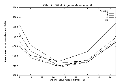
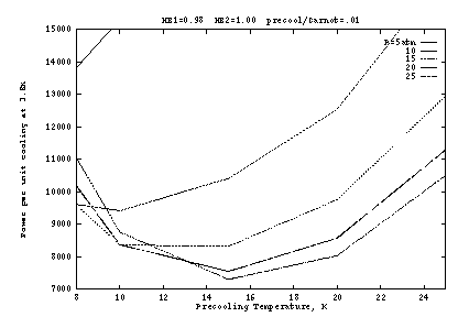
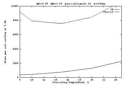
Figure 2 shows the input work per unit cooling if the heat exchangers
are ideal (![]() ), as a function of the pre-cooling
state
), as a function of the pre-cooling
state ![]() . Here the precooler efficiency is taken as 1% of
Carnot, which is typical of small G-M cryocoolers for this temperature
range. The optimum occurs at about
. Here the precooler efficiency is taken as 1% of
Carnot, which is typical of small G-M cryocoolers for this temperature
range. The optimum occurs at about ![]() K and
K and ![]() atm. The
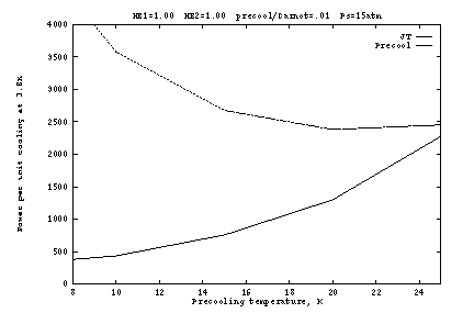
work is shown separately for the precooler and the J-T compressor in
Figure 2b, as a function of
atm. The
work is shown separately for the precooler and the J-T compressor in
Figure 2b, as a function of ![]() at fixed
at fixed ![]() atm. At lower
atm. At lower
![]() , the J-T work is reduced but at a high cost in precooler work.
As
, the J-T work is reduced but at a high cost in precooler work.
As ![]() increases, the J-T cooling per unit mass generally increases,
allowing lower mass flow and hence lower pre-cooling power; but above
about 10 atm this is overcome by the inverse J-T effect, so that
pre-cooling power must nevertheless increase slightly. At very high
pressures (above about 20 atm), the inter-atomic attraction responsible
for the J-T effect starts to be reversed (becoming a repulsion) and
the J-T efficiency decreases, requiring higher flow for a given amount
of cooling. But as Figure 2a shows, the pressure dependence is fairly
weak.
increases, the J-T cooling per unit mass generally increases,
allowing lower mass flow and hence lower pre-cooling power; but above
about 10 atm this is overcome by the inverse J-T effect, so that
pre-cooling power must nevertheless increase slightly. At very high
pressures (above about 20 atm), the inter-atomic attraction responsible
for the J-T effect starts to be reversed (becoming a repulsion) and
the J-T efficiency decreases, requiring higher flow for a given amount
of cooling. But as Figure 2a shows, the pressure dependence is fairly
weak.
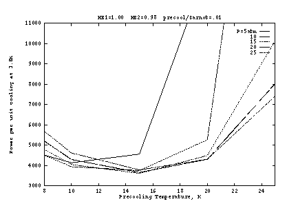
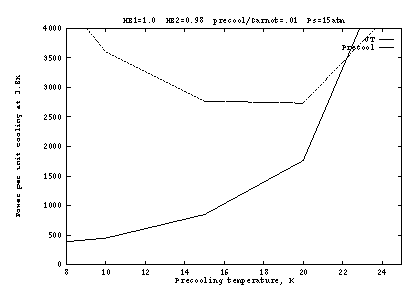
Figures 3 and 4 show the effect of imperfect heat exchangers. In
Figure 3 the final heat exchanger (![]() to the J-T orifice) is
degraded to 98%; and in Figure 4 the pre-cooling heat exchanger
(
to the J-T orifice) is
degraded to 98%; and in Figure 4 the pre-cooling heat exchanger
(![]() to the J-T orifice) is degraded to 98%. At
to the J-T orifice) is degraded to 98%. At ![]() K, a
few percent loss in the final heat exchanger is not significant
because the enthalpy change
K, a
few percent loss in the final heat exchanger is not significant
because the enthalpy change ![]() is a small fraction of
the heat of vaporization (heat absorbed from the load). At higher
precooling temperatures, and especially at lower pressures, the
enthalpy change is larger so that a few percent loss in the heat
exchanger causes a large loss of efficiency; above about 20K and below
about 10 atm, it becomes impossible to reach 3.8K when
is a small fraction of
the heat of vaporization (heat absorbed from the load). At higher
precooling temperatures, and especially at lower pressures, the
enthalpy change is larger so that a few percent loss in the heat
exchanger causes a large loss of efficiency; above about 20K and below
about 10 atm, it becomes impossible to reach 3.8K when ![]() .
.
When HE1 is degraded (Fig. 4), the J-T circuit efficiency is not
affected, but the precooler work increases substantially at all
temperatures and pressures. This is because the supply gas exiting
HE1 is at a higher temperature, requiring more cooling to reach ![]() .
For example, at
.
For example, at ![]() atm and
atm and ![]() K, we get
K, we get ![]() K if
K if
![]() ; but we get
; but we get ![]() K if
K if ![]() , so that the
drop across the precooler has increased from 1.8K to 5.6K. The
overall power required is thus very sensitive to the efficiency of the
first heat exchanger.
, so that the
drop across the precooler has increased from 1.8K to 5.6K. The
overall power required is thus very sensitive to the efficiency of the
first heat exchanger.
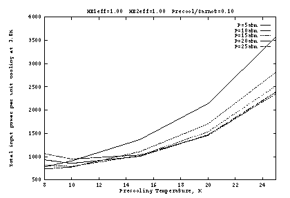
The above conclusions are dependent on the assumption that the
precooler is rather inefficient (only 1% of Carnot), so that its
power requirements dominate (Figs. 2b, 3b, 4b). The situation is
somewhat different with a more efficient precooler, as shown in Figure
5. Here the heat exchangers are again perfect, but the precooler
operates at 10% of Carnot. Since precooling is no longer so
expensive, it becomes advantageous to operate at lower ![]() , with the
optimum around 10K. The optimum supply pressure is still 10 to
15 atm, with weak dependence.
, with the
optimum around 10K. The optimum supply pressure is still 10 to
15 atm, with weak dependence.
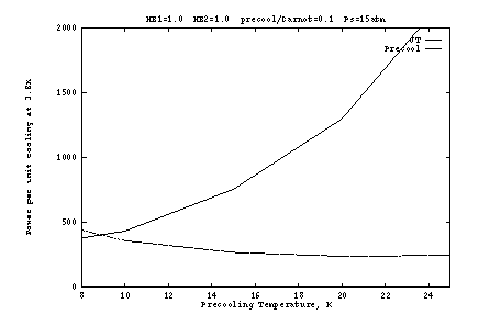
Finally, it is instructive to consider the size of the load on the
precooler. Figure 6 shows ![]() under selected conditions.
Except in the inefficient regime
under selected conditions.
Except in the inefficient regime ![]() K, we see that the precooling
load is 1.2 to 1.5 times the 3.8K capacity. A value of 1.5 is a good
rule-of-thumb for design work.
K, we see that the precooling
load is 1.2 to 1.5 times the 3.8K capacity. A value of 1.5 is a good
rule-of-thumb for design work.
Practical Considerations
As mentioned earlier, existing systems usually use more than one precooling stage. It is typical to have one additional stage at 50 to 80K. But whereas helium behaves nearly as an ideal gas in the range
300K to 50K, a set of perfect heat exchangers will cause the supply
gas to be delivered to the additional precooler at its temperature, so
that no heat is absorbed by there. In that case, we might as well
have a single heat exchanger from ambient to ![]() , as in the model of
Figure 1. However, 300K to 15K is a large range for one heat
exchanger. In practice, it might be difficult to achieve the required
high efficiency (
, as in the model of
Figure 1. However, 300K to 15K is a large range for one heat
exchanger. In practice, it might be difficult to achieve the required
high efficiency (![]() ) in a reasonably small device. The
density of helium also changes by a factor of 20 over this range, so
constructing the heat exchanger with tubes of constant cross section
will cause them to be either too restrictive at the warm end or too
large at the cold end. It therefore might be more practical to split
HE1 into two parts, allowing the warmer part to be fairly inefficient
(in order to keep it small) and including a precooler near 70K. The
inefficiency will require the 70K precooler to absorb some heat, but
since cooling at this temperature requires relatively low power the
tradeoff might be reasonable. Available space and design effort can
then be put into making the second part of the heat exchanger (70K to
) in a reasonably small device. The
density of helium also changes by a factor of 20 over this range, so
constructing the heat exchanger with tubes of constant cross section
will cause them to be either too restrictive at the warm end or too
large at the cold end. It therefore might be more practical to split
HE1 into two parts, allowing the warmer part to be fairly inefficient
(in order to keep it small) and including a precooler near 70K. The
inefficiency will require the 70K precooler to absorb some heat, but
since cooling at this temperature requires relatively low power the
tradeoff might be reasonable. Available space and design effort can
then be put into making the second part of the heat exchanger (70K to
![]() ) very efficient, since this has the biggest effect on overall
power consumption.
) very efficient, since this has the biggest effect on overall
power consumption.
The analysis also suggests some considerations for the J-T compressor.
Although the optimum supply pressure is around 15 atm, degradation is
slow as this pressure is reduced. Performance is essentially the same
at 10 atm, and overall power is only 3% higher at 5 atm (Fig. 3b, at
![]() K). By operating at 5-10 atm, the compression ratio is kept
to 8-15 (for 3.8K with
K). By operating at 5-10 atm, the compression ratio is kept
to 8-15 (for 3.8K with ![]() atm), allowing a single stage to be
used. This greatly reduces cost and complexity compared with
two-stage systems. In addition, consideration should be given to
using a reciprocating compressor rather than a rotary one. By having
one or more cylinders of high total displacement, a given flow rate
can be achieved at low speed. The process then becomes closer to
isothermal, with cooling during compression, which is considerably
more efficient than adiabatic. Reciprocating compressors are
generally considered to be less reliable than rotary ones because the
former have more wear-limited moving parts; but the lower speed and
lower operating temperatures may mitigate this when specific machines
are compare.
atm), allowing a single stage to be
used. This greatly reduces cost and complexity compared with
two-stage systems. In addition, consideration should be given to
using a reciprocating compressor rather than a rotary one. By having
one or more cylinders of high total displacement, a given flow rate
can be achieved at low speed. The process then becomes closer to
isothermal, with cooling during compression, which is considerably
more efficient than adiabatic. Reciprocating compressors are
generally considered to be less reliable than rotary ones because the
former have more wear-limited moving parts; but the lower speed and
lower operating temperatures may mitigate this when specific machines
are compare.

References and Notes
[1] A. Gibson, ``J. T. Loop Design Notes.'' Report RPP 2319(L), Division of Radiophysics, CSIRO, Sydney, Australia, June 1979.
[2] W. Higa and E. Wiebe, ``One million hours at 4.5 Kelvins.'' National Bureau of Standards Publication No. 508, pp 99-107, April 1978.
[3] M. Britcliffe, ``Two-watt, 4-Kelvin closed cycle refrigerator performance.'' TDA Progress Report 42-91, Jet Propulsion Laboratory, Pasadena, Jul-Sep 1987.
[4] L. D'Addario, ``Joule-Thompson refrigerator performance vs. heat exchanger efficiency.'' Report based on work at CSIRO and NRAO, July 1986, unpublished.
[5] D. Schroeter and J. Lamb, ``Characterization and optimization of the NRAO/Balzer three stage closed cycle JT refrigerator.'' EDIR No. 297, NRAO, Green Bank, Nov 1994.
[6] Neglecting the pressure drop is justified by calculations in [4] and also by tests on a small, experimental J-T refrigerator (unpublished notes, 1987).
[7] E.W. Lemmon, M.O. McLinden and D.G. Friend, ``Thermophysical Properties of Fluid Systems'' in NIST Chemistry WebBook, NIST Standard Reference Database Number 69, Eds. W.G. Mallard and P.J. Linstrom, March 1998, National Institute of Standards and Technology, Gaithersburg MD 20899 (http://webbook.nist.gov).
[8] T. R. Strobridge, 1974, ``Cryogenic refrigerators -- an updated survey." National Bureau of Standards Tech. Note 655.
[The following is an exposition of the concept of enthalpy and its usefulness in calculations of the sort considered in this memo. I include it here because I have been unable to find an equivalent explanation in a textbook.]
Consider the situation illustrated in Figure A1, where there is a continuous flow of fluid past boundary 1 into region X, and then out of region X past boundary 2. Let X be closed so that no fluid enters or exits via any other boundary. Inside X, the fluid may exchange work or heat or both or neither with the external environment. Since the flow is continuous, we consider the effect on a small element of fluid consisting of a fixed set of molecules.

Figure A1. Illustration of the notation used to explain the concepts of enthalpy and flow work.
The element is pushed past boundary 1 by the fluid that follows it, and it pushes on the fluid ahead of it when it passes boundary 2. Thus, the element does net work on the preceeding and following fluid in an amount

where ![]() is the area of boundary i,
is the area of boundary i, ![]() is the fluid pressure
there, and
is the fluid pressure
there, and ![]() is the distance that the element must move to pass
boundary i. Since
is the distance that the element must move to pass
boundary i. Since ![]() is the volume of the element at
boundary i, we also have
is the volume of the element at
boundary i, we also have

The first law of thermodynamics (conservation of energy) demands that the change of internal energy of the fluid element be given by

where ![]() ,
, ![]() is the external
work done by it while in region X, and Q is the heat flow into it
while in region X. Substituting and rearranging gives
is the external
work done by it while in region X, and Q is the heat flow into it
while in region X. Substituting and rearranging gives

Notice that the LHS of the last equation is the change in a quantity that is a function only of the fluid state at one point, and not of the way in which it got to that state. We can therefore define a state variable H = U + PV, called enthalpy. From this development it should be clear that enthalpy is useful in analyzing continuous-flow systems. The change in enthalpy per unit mass between any two points in the system gives the net external energy input per unit mass. If it is known that the intervening process is adiabatic (Q=0), then the enthalpy change is the external work on the fluid (as in a compressor); and if it is known that the process involved no external work (as in a heat exchanger or orifice), then the enthalpy change is the external heat absorbed. Enthalpy may be thought of as similar to the internal energy U, except that the effects of work done by the fluid on itself (``flow work" PV) have been taken into account.