MMA Antenna Working Group
J. Lugten
P. Napier (Chair)
J. Bieging
J. Cheng
D. Emerson
M. Fleming
M. Holdaway
J. Kingsley
J. Lamb
J. Mangum
J. Payne
W. Welch
D. Woody
June 24, 1998
An updated strawman design for the overall optics layout for a 10 m MMA antenna is proposed. The design is approximately optimized for either of the off-axis feed geometries proposed in MMA memo 163; for one of the on-axis schemes the subreflector size and central blockage could be reduced. Formulas are given for the aberrations due to off-axis feed locations, as well as those due to mirror mis-alignment. The magnitude of the various aberrations is given for representative geometries, including the curvature of field which may be an important consideration for receiver design. Choosing the optimum optical parameters requires evaluating the relative importance of competing factors. For example, choosing a faster primary mirror improves the close packing performance of the telescope, but degrades the off-axis optical performance and increases the sensitivity to mis-alignments.
Introduction
This memo is an updated version of MMA memo 163 (Napier et al, 1996), and documents the current ideas of the MMA Antenna Working Group with respect to the overall optics layout and receiver cabin space for a 10 m MMA antenna. We would like comments from the other MMA working groups, especially the receiver group, as to the suitability of this concept. The current concept is shown in Figure 1 below, and representative dimensions are given in Table 1. Some of the considerations which have led to this concept are discussed below. It is likely that some of the details will change as the antenna design proceeds. However, the various options currently being considered for the antenna design will have less impact on the optimum optical parameters than will the choice of feed arrangement.
Choice of Cassegrain Geometry
The proposed geometry is a minimum-blockage Cassegrain geometry. This choice is driven primarily by the desire for low antenna noise (to match the low atmospheric opacities available on the 5000m site in Chile) and for high aperture efficiency. The minimum blockage aspects of the design include supporting the quadrupod legs near the edge of the reflector and making the diameter of the subreflector equal to the diameter of the hole in the center of the primary reflector. The use of the Cassegrain focus avoids additional reflectors and their unavoidable contributions to the system temperature. At the Cassegrain focus it is possible to have more than one feed at a time looking at the subreflector. This is necessary, for example, if one wishes to monitor the atmospheric total power fluctuations at one frequency in order to correct for atmospheric phase fluctuations at another frequency.
Choice Of Primary Mirror Focal Ratio
The choice of 0.38 for the primary F/D is driven by the trade off
between close packing (short interferometer baseline without the
possiblility of antenna collisions) and sensitivity to mis-alignment.
For the geometry described, the antennas can be placed on a baseline
of length 1.28 D
without possibility of collision at elevation angles greater than
![]() . At an elevation of
. At an elevation of ![]() the shortest
baseline without possibility of collision is 1.32 D. All of the
antenna designs currently being studied meet or exceed this close
packing performance.
the shortest
baseline without possibility of collision is 1.32 D. All of the
antenna designs currently being studied meet or exceed this close
packing performance.
Possible Feed Arrangements and Secondary Mirror Magnification
The location of the cassegrain focus is chosen to lie 1.5 m below the vertex of the primary to allow plenty of space in front of the receiver for the various selectable quasi-optical devices that have been proposed. Examples of these devices include calibration devices, circular polarizers, solar observing devices, dual frequency reflectors and possibly a beam directing reflector for the 30 GHz receiver which could be mounted off to the side of the mm/submm receiver. The receivers are located near the elevation axis so that antenna balance is not substantially affected by their removal. Designs with better antenna close packing performance either have less space available in front of the receivers or locate the receivers aft of the elevation axis.
Several feed systems can be considered to provide the ten receiver bands proposed over the 30 GHz to 950 GHz range proposed for the MMA (Wootten et al, 1998). Four possible systems and some of their advantages and disadvantages were discussed in memo 163. They are a) off-axis feeds with a symmetrical subreflector, b) off-axis feeds with a rotating asymmetric subreflector, c) movable dewar(s) which place the selected feed on axis, or d) a rotating, cooled on-axis beam director.
The magnification of the secondary mirror is chosen so that the diameter of the subreflector is equal to that of the hole in the primary. For either of the off-axis feed geometries (scheme a or b), the optimum secondary mirror diameter is about 0.762 m (30 inches) allowing a clear aperture through the primary of 0.660 m (26 inches) diameter. This geometry gives a central blockage of 0.58% of the geometrical area. Using an on-axis optical scheme (scheme c or d) would allow a smaller secondary. The effect of subreflector size on the nutation performance requires further study.
Aberrations
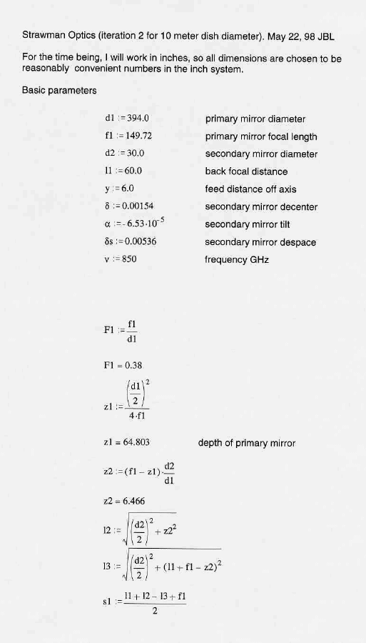
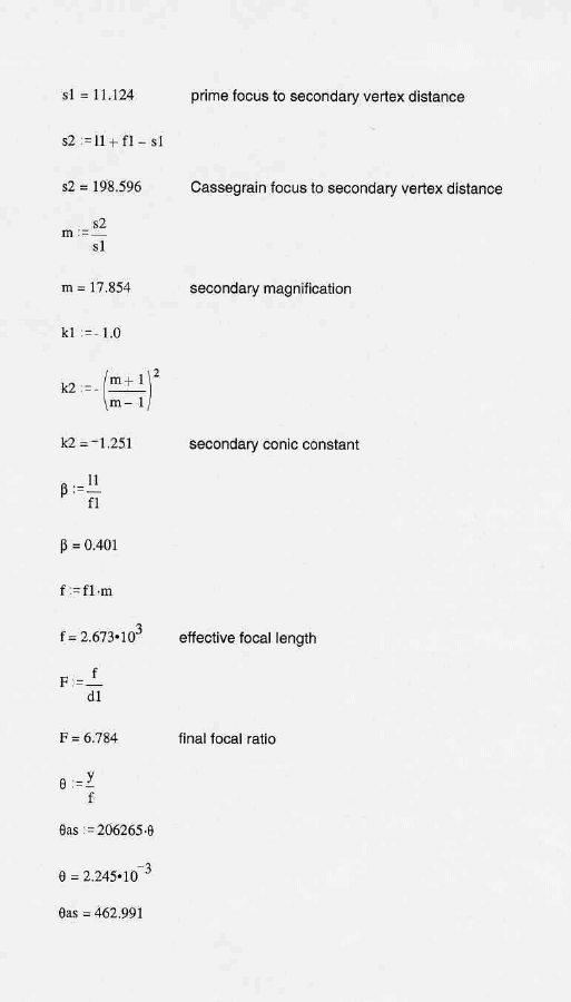
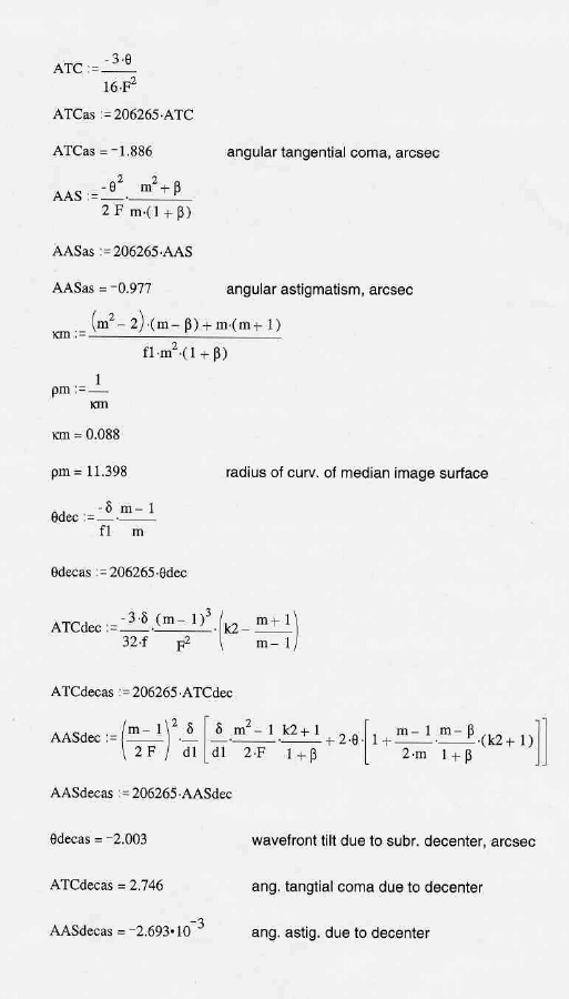
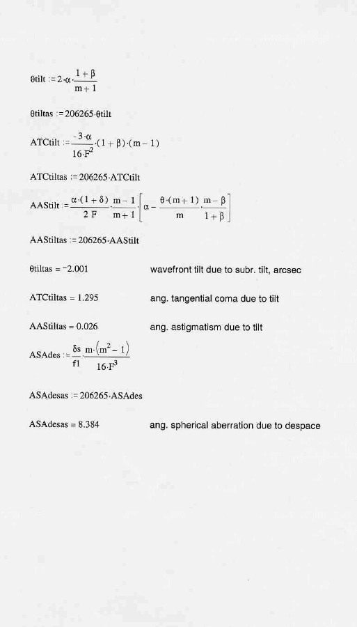
The optical configuration described here is the classical cassegrain type. The main parameters are summarized in Figure 1 and Table 1. The classical cassegrain configuration has zero spherical aberration but suffers from both coma and astigmatism off axis. Figure 2 is a Mathcad spreadsheet which gives general formulas for aberrations, which are taken from Schroeder (1987) and from Faber (1981). The relationship between the angular aberrations given by these formulas and the wavefront rms deviation are derived in Lugten (1998).
For a feed located 0.152 m (6 inches) off axis, the angular tangential coma (ATC) is 1.89 '' '' and the angular astigmatism (AAS) is 0.98 '' '' . This results in wavefront errors of 1.80 microns RMS and 2.42 microns RMS, respectively, assuming uniform illumination. These wavefront errors result in a loss of on axis gain of 0.10% and 0.19%, respectively at 850 GHz (353 microns wavelength). With tapered illumination, the RMS wavefront errors are slightly smaller. The radius of curvature of the median image surface is 0.290 m (11.4 inches), so that for a feed located 0.152 m off axis the median image surface is approximately 0.043 m (1.7 inches) closer to the secondary mirror than for a feed located on axis. If receiver feeds were to be configured for a flat median image surface and the subreflector moved to bring the selected feed into focus, a subreflector motion of 136 microns (0.0054 inches) is required. This motion would introduce 8.4 '' '' of angular spherical aberration (ASA), which corresponds to 3.79 microns RMS wavefront error and would result in a 0.45/ Misalignment of the telescope also produces aberrations. Decenter of the subreflector by 39 microns produces a wavefront tilt (pointing error) of 2 '' '' and ATC of 2.75 '' '' , and negligible AAS. Likewise, tilt of the subreflector by 13.5 '' '' produces a wavefront tilt of 2 '' '' and ATC of 1.30 '' '' and negligible AAS. The aberrations resulting from tilt and decenter of the subreflector are strongly coupled - for example, a combination of tilt and decenter equivalent to a rotation of the subreflector about the prime focus location produces nearly perfect cancellation of aberrations. Finally, as noted above, despace of the mirrors by 136 microns produces 8.4 '' '' of angular spherical aberration (ASA) resulting in a loss of forward gain of 0.45% at 850 GHz.
For the classical cassegrain configuration, ATC varies as the inverse square of the final focal ratio. AAS varies approximately inversely with the primary mirror focal ratio as does the curvature of the image surface. Thus, choosing a faster primary mirror increases AAS and increases the image surface curvature. Likewise, ATC due to secondary decenter or tilt is worse for a faster primary mirror, and ASA is more sensitive to despace errors for a faster primary mirror.
Conclusions
A strawman design for the overall optics layout of the MMA antenna is proposed. Sufficient detail is provided to allow design of the receiver and its feed layout to proceed. Careful evaluation of the relative importance of various performance goals is required, because improving one usually degrades others.
Figure 1: MMA Optical Configuration, Version 2.
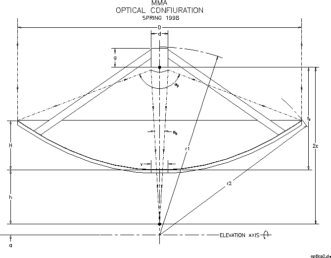 | |||
| D | Primary Diameter | 10.01 m | 394.00 inches |
| fp | Focal length of primary | 3.803 m | 149.72 inches |
 of primary of primary | 0.38 | 0.38 | |
| d | Secondary diameter | 0.762 m | 30.00 inches |
| Final f/D | 6.78 | 6.78 | |
| Magnification factor | 17.85 | 17.85 | |
| | Primary angle of illumination | 133.36 deg | 133.36 deg |
 | Secondary angle of illumination | 8.44 deg | 8.44 deg |
| 2c | Distance between primary and secondary foci | 5.327 m | 209.72 inches |
| H | Depth of primary | 1.646 m | 64.803 inches |
| r1 | Tipping structure apex radius (1" clearance) | 6.624 m | 260.8 inches |
| [close packing 1.32 D] | |||
| r2 | Tipping structure dish radius (1" clearance) | 6.388 m | 251.5 inches |
| [close packing 1.28 D] | |||
| h | Distance from vertex to secondary focus | 1.524 m | 60.00 inches |
| a | Distance from elevation axis to focus | 0.762 m | 30.00 inches |
| g | Distance from primary focus to top of quadrapod | 0.508 m | 20.0 inches |
| v | Clear aperture through primary | 0.660 m | 26.0 inches |
References
Faber, Sandra M., ``Formulae Relevant to the Optical Performance of Telescopes'', U.C. TMT Report No. 55 (1981)
Lugten, John B., ``Relationships between Angular Aberratiions and the Wavefront Deviation from Flatness'', MMA memo in prep. (1998)
Napier, P. et al., ``A Strawman Optics Layout for the MMA Antenna'', MMA memo 163 (1996)
Schroeder, Daniel J., ``Astronomical Optics'', Academic Press, San Diego (1987)
Wootten, A., Snyder, L., van Dishoeck, E., and Owen, F., ``Frequency Band Considerations and Recommendations'', MMA White paper (1998)
