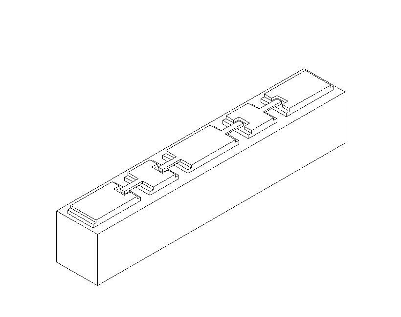
Figure 1. Sketch of a UVA GaAs chip containing four varactors.
Richard F. Bradley
National Radio Astronomy Observatory
April 30, 1998
1. Introduction
The conventional approach to generating local oscillator (LO) power for millimeter- and submillimeter-wave heterodyne mixers is to generate power at a lower frequency using a suitable phase-locked source, and to convert this power to the desired commensurate frequency using a nonlinear diode such as a varactor in a frequency multiplier circuit. Although useful for single-dish telescope receiver systems, the conventional approach, using current state-of-the-art components, is highly impractical for large array-type radio telescopes for which manageable cost and high reliability are important factors.
In order to improve upon reliability and decrease cost, the limitations of the two basic components in the LO system, namely the oscillator and the frequency multiplier, must be carefully examined. For the power source, the mainstay is the Gunn-effect oscillator which has been used successfully for many years because of its adequate output power, inherently low amplitude noise characteristics, and electronic fine tuning making it well suited for phase-locked circuitry. However, for large array applications, its usefulness is somewhat compromised since the coarse tuning is accomplished through mechanical adjustment of a high-Q resonant cavity. It is an expensive task to make this mechanical adjustment automated, accurate, repeatable, and reliable. Also, such cavity systems can suffer from unwanted moding which results in narrow frequency bands in which the output power can drop to very low levels. The mechanical tuning is limited in range as well, and, hence, several Gunn oscillators are needed to cover a given waveguide band. The maximum operating frequency of second harmonic Gunn oscillators is about 150 GHz, and so to reach millimeter and submillimeter wavelengths, frequency multipliers are required. State-of-the-art multipliers are limited in performance because of several factors, including: narrow instantaneous bandwidth requiring mechanically-adjustable tuning structures that may reduce reliability, low conversion efficiency leading to difficulties in power distribution, use of point-contacted varactors which are mechanically fragile structures, and intricate mechanical details making component assembly rather difficult. Overcoming these limitations is essential if conventional LO systems are to be made practical for the MMA.
All-electronic LO tuning has the advantage of improving reliability for array systems at a modest cost. The most useful all-electronic power source up to 50 GHz is the Yttrium-Iron-Garnet (YIG) tuned FET oscillator (YTO). A YTO can be tuned over a very broad band and it can easily be phase-locked to a reference source. A chain consisting of a YTO, followed by wideband, fixed-tuned frequency multipliers and low noise power amplifiers, forms a viable alternative to a Gunn oscillator chain. Wideband monolithic HFET power amplifiers are becoming increasingly more common up to 100 GHz, primarily due to current military and commercial demands for systems operating in this frequency range. However, the development of wideband frequency multiplier technology has lagged behind in development. Advances in this area will determine the success of future YTO-based millimeter- and submillimeter-wave LO systems.
Over the past few years, the single most important factor influencing future frequency
multiplier development has been the advent of versatile computer-aided design packages,
enabling the design engineer to analyze complex electromagnetic structures, create and simulate
detailed equivalent circuit models, and predict semiconductor transport properties, all to a high
degree of accuracy. For the first time, the nonlinear dynamics of the varactor, the electrical
properties of the semiconductor package, and the embedding circuitry of the multiplier can be
analyzed together as a complete frequency multiplier circuit. Very successful millimeter
wavelength multiplier circuits have recently been developed by Porterfield et al. [1] and Erickson
[2] based on calculations using modern computer-aided design tools. Upon applying such tools,
one begins to understand the reasons behind the limitations of existing multiplier designs, thus
opening the door to exploring new approaches and techniques never before possible in order to
meet the stringent demands placed on the LO system by the MMA specifications.
2. Specifications for the MMA LO System
The NRAO MMA is a good example of a new generation array radio telescope whose
requirements will drive millimeter- and submillimeter-wave local oscillator development for
years to come. Reliability is an important issue not only because of the number of components
required but also due to the remoteness of the observing site [3]. Reliability can be greatly
enhanced by using all-electronic tuning and by replacing the fragile point contact varactor with
the more rugged planar varactor. Due to the relatively large current densities in varactors, anode
temperatures can reach well over 100 degrees C above ambient, thus compromising the long-term lifetime. The lifetime can be increased indefinitely through the use of cryogenic cooling
which is typical in modern receivers and therefore should not increase the cost of the LO.
However, the cost of building frequency multipliers is rather large due to the current complexity
of the micro fabrication required. This cost can be reduced substantially at the circuit design
stage by using monolithic (MMIC) technology [4], minimizing the machining operations
required, and reducing the need for close tolerances during machining steps so that efficient
duplication can be achieved. Finally, the higher-frequency multipliers should be designed as
cascaded components of doublers and triplers for interchangeability. Further requirements on
frequency bands, output power, amplitude noise, and phase noise will now be examined.
2.1 Frequency Requirements
A proposed band plan for the MMA is shown in Table 1. The first three columns
indicate the type of receiver, either HFET for the lower frequencies or SIS for the higher
frequencies, the RF band, and the RF band-delimiting frequency ratio defined as fmax/fmin for each
band. The highest frequency band is a future possibility and is not planned to be implemented as
part of the initial construction. Assuming an IF band from 4-12 GHz, columns four and five
show the LO tuning range required and the LO band-delimiting frequency ratio defined as
fmax/fmin for each LO range. A prime feature of this plan is that all LO frequencies above 60 GHz
can be derived from two phase-locked sources: #1 covering the range 60-90 GHz, and #2
covering 80-120 GHz. It should be noted that since the noise of SIS mixers may increase with
IF frequency, the sensitivity of the radiometer for spectral line observations may be improved
somewhat if only the lower portion of the IF band is used. The LO tuning range required to
achieve optimum sensitivity may therefore be greater than that shown in Table 1.
| Receiver Type | Frequency Range
[GHz] |
Frequency Ratio | LO Range
[GHz] |
LO Frequency Ratio |
| HFET | 33- 50 | 1.52 | 55- 64 | 1.16 |
| HFET | 68- 90 | 1.32 | 90-104 | 1.16 |
| HFET | 90-116 | 1.29 | 76- 94 | 1.24 |
| SIS | 125-175 | 1.40 | 137-163 | 1.19 |
| SIS | 175-245 | 1.40 | 187-233 | 1.25 |
| SIS | 245-320 | 1.31 | 257-308 | 1.20 |
| SIS | 320-416 | 1.30 | 332-404 | 1.22 |
| SIS | 416-510 | 1.23 | 428-498 | 1.16 |
| SIS | 602-720 | 1.20 | 614-708 | 1.15 |
| SIS | 787-950 | 1.21 | 799-938 | 1.17 |
2.2 Power Requirements
A specification for the LO power level is derived from the pump power required by the SIS mixers which is approximately 1 µW. In the worst-case scenario where only single-ended SIS mixers are used, a waveguide or quasi-optical LO coupler, having a coupling factor of -20 dB, will be required to combine the LO with the RF signal. As a result, the amount of LO power required at the input of the receiver will be approximately 100 µW. An estimate of frequency conversion efficiencies that form realistic yet challenging goals for new broadband, fixed-tuned, planar frequency multiplier designs is given in Table 2. The first three columns give the LO tuning range from Table 1, the driving source along with its tuning range, and the multipliers needed. Columns four and five give the multiplier efficiency and output power for a driving power of 50 mW.
It is proposed that each receiver of a dual-polarization system be equipped with a
separate multiplier chain that is driven by a common source. The minimum required output from
the single phase-locked source will therefore be 100 mW. Such pairing of the multiplier chains
with the receivers has the following benefits: 1) switching of the LO source at 100 GHz rather
than at the higher LO output frequency minimizes the losses associated with the long waveguide
runs inside the dewar, the vacuum window, and the waveguide switch, 2) multiplier chains
could be tied to the cryogenic refrigeration system to improve conversion efficiency and increase
the varactor lifetime, and 3) an LO leveling circuit, perhaps using the SIS mixer current in a
servo loop while adjusting the bias current on the frequency multipliers, could be incorporated
into each multiplier chain. Given the expected performance of the multipliers, the available
dynamic range is shown in column six of Table 2. This dynamic range can be increased
substantially if balanced mixers are used [6], since the RF and LO ports will then be separated,
eliminating the need for the -20 dB LO coupler. With this configuration, the dynamic range will
not be compromised at the higher operating frequencies.
| LO Tuning
Range [GHz] |
Drive Source
& Tuning [GHz] |
Multiplication
Factor |
Conversion
Efficiency [percent] |
Output
Power [mW] |
Power Leveler
Dynamic Range [dB] |
| 137-163 | #1 68- 82 | X2 | 30 | 15 | 22 |
| 187-233 | #2 93-117 | X2 | 20 | 10 | 20 |
| 257-308 | #2 85-103 | X3 | 5 | 2.5 | 14 |
| 332-404 | #2 83-101 | X2, X2 | 20, 10 | 1.0 | 10 |
| 428-498 | #1 71- 83 | X2, X3 | 30, 3 | 0.45 | 6.5 |
| 614-708 | #2 102-118 | X2, X3 | 20, 3 | 0.30 | 4.8 |
| 799-938 | #2 99-118 | X2, X2, X2 | 30, 15, 5 | 0.010 | 0 |
2.3 Amplitude Noise
The specification for LO amplitude noise is to meet an acceptable value for the gaussian noise that will be added to the front-end noise of the SIS receiver. The contribution of LO noise to the HFET front-ends will be negligible. The mixer LO noise manifests itself as noise sidebands associated with the CW source, but far enough away from it that the noise will ultimately appear in the RF passband of the receiver. It has been suggested that the LO amplitude noise contribution to the noise temperature of a single-ended SIS mixer be limited to one degree Kelvin, and with a typical LO pump power of 1 µW per mixer, a specification of 1 Kelvin per microwatt is therefore defined. On a per hertz basis, this noise specification translates to an LO signal-to-noise ratio (SNR) of 168 dB. A relatively low-Q bandpass filter, centered about the signal frequency, can be used to reduce this noise if needed. If balanced mixers are used, the specifications for the filter can be relaxed in proportion to the LO isolation that is provided, typically on the order of 10 to 20 dB, or perhaps eliminated entirely.
There has been some concern about the amount of phase and amplitude noise
generated by power amplifiers. However, recent measurements by J. Kooi [7] on a 92-97 GHz
MMIC power amplifier indicate this additional noise is quite small.
2.4 Phase Noise
The dominant contributor to the phase fluctuations encountered by the MMA will be atmospheric fluctuations along the line of sight of the instrument. Two distinct methods [8] are currently being considered for phase calibration: 1) Fast Phase Calibration (FPC) and 2) Radiometer Phase Correction (RPC). FPC involves observing an astronomical calibrator on time scales short enough that the atmosphere does not change significantly between calibrations and using calibrators close enough to the target source that the path through the lower troposphere responsible for the phase fluctuations is essentially the same. FPC corrects for fluctuations on time scales longer than the time period between calibrations. The 11.2 GHz satellite phase monitors currently used for site surveys have baselines of 100 m and 300 m and thus directly sample the atmospheric structure function appropriate for evaluating the utility of the FPC technique. The technique works because the dominant atmospheric fluctuations correspond to structure in the atmosphere on the scale size of the baseline and on time scales given by the wind crossing time. An added benefit is that calibrating on a 10-second time scale greatly decreases the effect of temperature and other slow fluctuations on the phase stability of the antenna and electronics. However, the most likely frequency for calibration will be the 90 GHz band or perhaps even lower due to the limited availability of suitable astronomical calibration sources at millimeter wavelengths, so it is important that the LO system be built such that phase calibration at one frequency will also correct for drifts in the LO chains for the other bands as much as possible.
RPC is based upon scientific evidence that the dominant source of path length variations at millimeter wavelengths is fluctuations in the water vapor along the line of sight and that this water vapor can be measured by its continuum or line emission. This method requires radiometer/receiver systems with sufficient stability. RPC works on time scales of approximately one second up to the time scale set by the radiometer stability. A special radiometer, dedicated to monitoring the 183 GHz water line, is currently being considered.
Based upon the requirements of the proposed phase calibration methods, as well as the need to use holography to measure the surface features to the desired accuracy of better than 8 µm (wavelength/100), the resulting phase stability specification for the electronics, as defined by the MDC Phase Calibration Working Group, is 3 degrees over time scales greater than 1 second. This specification will be used as a guideline for MMA LO development. However, specifications for allowable phase fluctuations on time scales shorter than one second have not yet been defined. Integration-and-dump times, associated primarily with mosaicing operations, will be the defining factor for this specification.
3. Development Plan Overview
The conventional LO development plan is divided into four Technical Development
Areas (TDA) as follows:
3.1 TDA I: Frequency Multipliers using Discrete Planar Varactors
TDA I of the development program will focus on broadband, fixed-tuned frequency doublers used to extend the phase-locked loop LO system to cover the 137-163 GHz and
187-233 GHz bands. Frequency doublers for these bands will be based on the highly successful
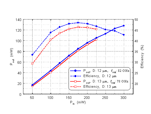
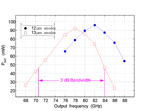
40/80 GHz design [1] which uses a balanced planar varactor chip from the Semiconductor Device Laboratory of the University of Virginia (see Fig. 1). The measured results are shown in Fig. 2 for room temperature operation. The peak efficiency increased to more than 60 percent upon cooling the doubler block to 20 K.

Figure 1. Sketch of a UVA GaAs chip containing four varactors.
There are currently two new designs for TDA I already in progress: 55/110 GHz and 110/220 GHz for use in a 690 GHz heterodyne tipping radiometer [9]. These designs will become the first iteration of the MMA designs. Figure 3 shows a sketch of the 110/220 GHz block.
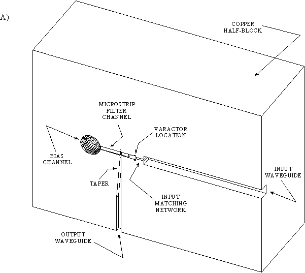
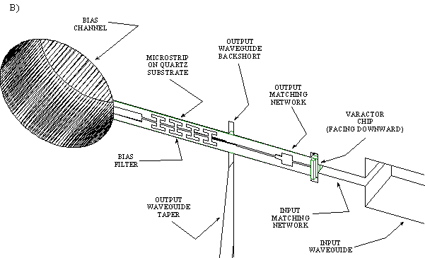
Figure 3. Sketch of 110/220 GHz doubler. A) one-half of the split block design and B) details of microstrip circuitry.
Future iterations will be concerned with increasing the ouput power of the doublers and
increasing the operational bandwidth as well as making the designs easier to fabricate. Designs
using discrete planar varactors are limited to about 250 GHz because the size of the chip package
becomes electrically large and therefore the multiplier circuit becomes exceedingly more difficult
to tune properly over a wide bandwidth.
3.2 TDA II: Frequency Multipliers using Monolithic Circuitry
TDA II of the development plan will focus on the doublers and triplers needed to extend the PLL LO up to 700 GHz. Because of the short wavelengths involved, these designs will require some level of circuit integration (MMIC). Due to the high development costs of MMICs, sharing ideas and designs between groups is prudent and so we are exploring areas of common need among projects such as the MMA, FIRST/HIFI, etc. Recently, a collaboration was formed between the NRAO-CDL and NASA-JPL for MMIC multiplier development, where our experience in multiplier circuit design and electromagnetic simulation will be coupled with the MMIC fabrication experience of JPL. Two initial designs are currently under way:
a 200/400 GHz balanced doubler and a 220/660 GHz balanced tripler.
3.3 TDA III: LO Phase-Locked Source Development and Evaluation
The two phase-locked LO systems used to drive the frequency multipliers will now be described. A block diagram of the RF oscillator is shown in Fig. 4. The 100 mW, 60-90 GHz oscillator consists of a 10-15 GHz YTO followed by a doubler to 20-30 GHz, a 10 dB power amplifier, a tripler to 60-90 GHz, and a second 10 dB power amplifier. The 80-120 GHz oscillator consists of a YTO, doubler, and power amplifier to 20-30 GHz as in the previous case, but here it is followed by a doubler to 40-60 GHz, a 9 dB power amplifier, and a high power doubler. Both systems will require appropriate interstage filters and isolators. The bandwidth of the phase-locked sources may be limited by the availability of power amplifiers since research groups requiring such amplifiers are forced to share designs due to high development costs. It is not clear at this time how the MMA LO will be affected by amplifier availability.
Figure 5 shows a block diagram of the phase-locking circuitry and reference source that is common among the various systems. The output frequency of the unit is phased-locked to the sixth or eighth harmonic of a 10-15 GHz frequency synthesizer in the case of either 60-90 or 80-120 GHz operation, respectively. The synthesizer is, in turn, phased-locked to a reference source. The output of the harmonic mixer is the difference frequency of 100 MHz which is filtered and amplified before entering the In-Phase (I) & Quadrature-Phase (Q) detector. The other input port of the phase detector receives a signal from a 100 MHz phase reference that contains the required frequency offsets and phase changes for fringe rotation, sideband separation, and phase switching. The I and Q output of the phase detector are both low-pass filtered. The signal in the I channel, upon integration, is used to adjust the RF oscillator fine tuning to complete the phase-locked loop. The signal in the Q channel drives a lock detection circuit, which in turn controls the ramp generator used as a search oscillator. The search oscillator sweeps the fine tuning control voltage until the RF source is within the lock-in range of the loop. Upon successful lock, the search oscillator is disconnected and lock is indicated.
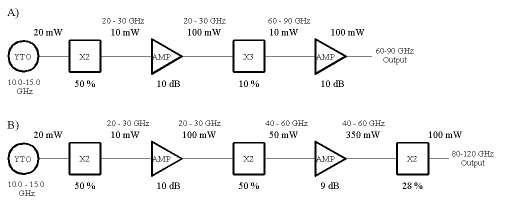
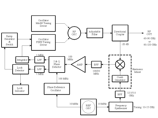
Understanding the noise contribution of the various approaches to generating LO power at 100 GHz is the focus of TDA III. The type of LO system that will meet the array noise performance specifications will have an enormous impact on the entire MMA system design, both in the degree of complexity and the overall cost. Furthermore, based on the measurements, a decision will be made regarding the highest frequency that can be included within the phase-locked loop; this decision will impact millimeter-wave harmonic mixers. To study PM noise, a standard phase noise measurement system will be constructed. This system will be based on the complete HP phase noise measurement system, including the necessary mixers to translate the
100 GHz signals down to the operating range of the instrument. A stable reference oscillator and
distribution system should also be purchased. For AM noise studies, a 100 GHz SIS mixer,
which is currently available at the NRAO-CDL, may be used. However, a balanced Schottky
system, dedicated specifically for AM noise measurement, would be quite useful, since the
system will not require cooling and the balanced nature of the design results in the LO noise
directed to a separate IF port for ease of measurement. Two YIG-based phase-locked oscillator/
amplifier/ multiplier chains as well as phase-locked Gunn-effect oscillators will be compared on
the basis of both AM and PM noise. TDA III will culminate with the demonstration of a
"breadboard version" of a suitable 100 GHz phased-locked LO system that meets the MMA
amplitude and phase noise specifications.
3.4 TDA IV: Functional Prototype LO Development
TDA IV of the development program will center on the "functional prototype" which is defined here as a complete LO system, ready for installation into the prototype MMA antenna system. TDA IV will build upon the breadboard version developed for TDA III; various modifications will be done to provide for locking to the distributed microwave reference signal, insure compatibility with fringe rotation functions, provide proper frequency control, and provide power leveling control. Size reduction and modular packaging will also be performed. Close coordination with the front-end, system, and control groups will be essential. This TDA will culminate with the demonstration of complete functional prototype units for the 60-90 and 80-120 GHz bands.
ACKNOWLEDGEMENTS
I wish to acknowledge John C. Webber, A. Richard Thompson, and S-K. Pan for
discussions leading to the present MMA conventional local oscillator plan. I also wish to thank
David Porterfield, Kamaljeet S. Saini and Donald G. Stone for their contributions to the
conventional frequency multiplier development effort at NRAO.
REFERENCES
1. D. W. Porterfield, T. W. Crowe, R. F. Bradley, and N. R. Erickson, "A High-Power, Fixed-Tuned, Millimeter-Wave Balanced Frequency Doubler," submitted to IEEE Trans. on
Microwave Theory and Techniques, Jan. 1998.
2. N. Erickson, "Wideband High Efficiency Planar Diode Doublers," Ninth Int. Symp. on Space
Terahertz Technology," Pasadena, CA, March 1998.
3. P. Napier and J. West, "High Altitude Medical and Operations Problems and Solutions for the
Millimeter Array," Proc. SPIE, 3349, 1998.
4. R. F. Bradley and R. J. Mattauch, "Planar Monolithic Schottky Varactor Diode Millimeter-Wave Frequency Multipliers," Technical Report RL-TR-92-187, Rome Laboratory, Air Force
Systems Command, Griffiss Air Force Base, NY, June 1992.
5. R. F. Bradley and D. W. Porterfield, "New Frequency Multipliers for Millimeter and
Submillimeter Wavelength Coherent Array Receiver Applications," Proc. SPIE, 3357, 1998.
6. S-K. Pan, private communication.
7. J. Kooi, private communication.
8. D. Woody, M. Holdaway, O. Lay, C. Masson, F. Owen, R. Plambeck, S. Radford, and E.
Sutton, "The MDC Phase Calibration Working Group Report," NRAO MMA Memo No. 144,
(http://www.cv.nrao.edu), Oct. 3, 1995.
9. R. F. Bradley and S-K. Pan, "690 GHz Tipping Radiometer: A Design Survey," NRAO Electronics Division Technical Note 171, Aug. 28, 1995.