Back to Memolist
9th Int. Symp. on Space Terahertz Tech., March 17-19, 1998
MMA Memo 206:AN INTEGRATED SIDEBAND SEPARATING SIS
MIXER FOR 200-280 GHz
A. R. Kerr1, S.-K. Pan1, and
H. G. LeDuc2
1National Radio Astronomy Observatory*
Charlottesville, VA 22903
2Jet Propulsion Laboratory
Pasadena, CA 91109
ABSTRACT
Separate waveguides for the signal and LO are connected via
suspended striplines to a 2 x 1 mm quartz substrate which contains all
the RF components of the sideband separating mixer: quadrature hybrid,
LO power splitter, two LO couplers, and two SIS mixers. These
components are realized in capacitively-loaded coplanar waveguide,
which minimizes stray coupling between adjacent components and
coupling to undesired modes in the thick quartz substrate. Over the
200-280 GHz band, the mixer noise temperature was 50-150 K and the
overall receiver noise temperature was 60 - 200 K (both measured
outside the vacuum window). The sideband separation was  9 dB, which we hope to improve by reducing leakage of LO power under the substrate into the signal port, and by improving the match of the cold termination of the fourth port of the input quadrature hybrid.
INTRODUCTION
With noise temperatures of SIS receivers now in the range 2-4 times the photon temperature (hf/k), the overall sensitivity of radio astronomy measurements can be seriously degraded by atmospheric noise. In spectral line measurements, atmospheric noise in the unwanted (image) sideband can be eliminated by using a sideband separating scheme. The benefits of such a scheme, in the context of interferometers and single-dish radio telescopes have been explored in [1] and [2].
An experimental 100 GHz sideband separating mixer using discrete
components -- a waveguide magic-T and two SIS mixers, with an adjustable phase-shifter in the LO path to one mixer -- was described in [3]. At shorter wavelengths, the signal and LO phasing can be done quasi-optically using various configurations described in [3]-[5], but even at 250 GHz the quasi-optical schemes are physically cumbersome and require a large cryostat if several receivers are to be attached to the same refrigerator. At the 1996 THz Conference we proposed a design for a single-chip sideband separating SIS mixer [5], and the present paper gives our first results.
In the microwave range, sideband separating mixers have been available commercially for many decades. The usual implementation is to divide the signal and LO power between two mixers using a quadrature hybrid in either the signal or LO path; here the former option is used as shown in Fig. 1. The IF outputs from the two mixers are combined in an IF quadrature hybrid, with the result that, ideally, all the downconverted power from the upper and lower sidebands appears separately at the two output ports of the IF hybrid.
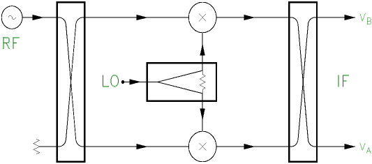
Fig. 1. Schematic diagram of a sideband separating mixer of the type used in this work.
The image rejection of such a sideband separating mixer depends on the
amplitude and phase imbalance through the parallel signal and LO
paths, including the IF quadrature hybrid, as analyzed in [5]. For
radio astronomy applications, the primary reason for using a sideband
separating mixer is to reduce atmospheric noise in the unwanted
sideband to an acceptable level, and this is accomplished with  10 dB of image rejection. An amplitude imbalance of 5.7 dB (for the whole circuit) or a phase imbalance of 35° results in an image rejection of 10 dB, so the required tolerance on components should not be a practical obstacle. An image rejection of 20 dB would result from an amplitude imbalance of 1.7 dB or a phase imbalance of 12°, numbers which may well be achievable using Nb integrated circuit technology.
DESIGN
The design of the sideband separating mixer was described in detail in
[5]. The complete RF circuit is on a 2 x 1 mm fused quartz substrate,
connected to signal and LO waveguides via suspended striplines on
separate substrates, as shown in Fig. 2. Connections between the
probes and the main substrate are by thin gold ribbons soldered to the
bonding pads. A Nb ground plane extends over most of the upper side of
the substrate, and has gold contact pads along all four sides. These
pads contact the mixer block through gold crush-wires which are
compressed as the block is assembled.
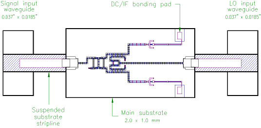
Fig. 5. The image separating mixer, showing the signal and LO waveguides, suspended stripline coupling probes, and the main substrate.
All the components and interconnections on the mixer chip are realized
using capacitively loaded coplanar waveguide (CLCPW) -- see Fig. 3. CLCPW has several advantages over microstrip and coplanar waveguide (CPW): On a quartz substrate it can have characteristic impedances in the range 10-100 ohms with dimensions convenient for standard optical lithography. All conductors are on the same side of the substrate and the energy is confined to a region close to the center conductor, which allows the use of a conveniently thick substrate. The periodic bridges are grounded at their ends, which effectively suppress coupling to the odd-mode which can occur in long CPW lines, and reduces coupling between adjacent components.
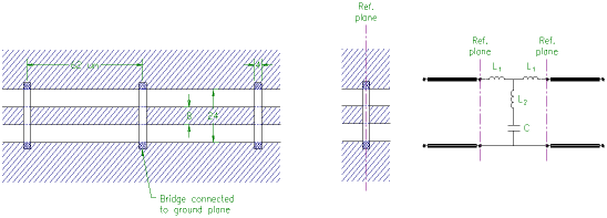 Fig. 3. A length of capacitively loaded coplanar waveguide (CLCPW). Dimensions are in microns.
A detailed view of the mixer substrate is shown in Fig. 4. The RF signal enters at the left CPW which makes a broadband transition to CLCPW. It is divided in the quadrature hybrid and passes into the mixers via the LO couplers. Similarly, the LO enters at the right CPW, then passes through a Wilkinson power divider to two ~17 dB LO couplers and into the SIS mixers. The individual components were designed using an electromagnetic simulator (Sonnet em) and a microwave circuit simulator (MMICAD) as described in [5].
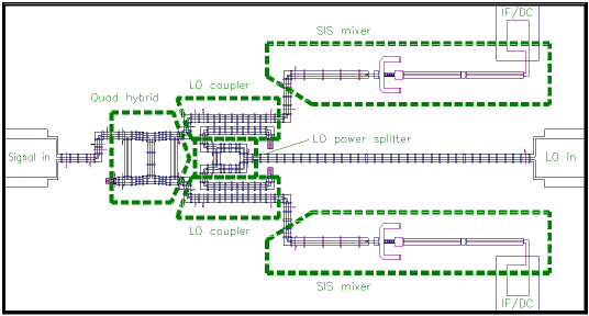
Fig. 4. Substrate of the sideband separating mixer, showing the main components. Most of the surface is covered by a ground plane.
To facilitate (eventual) operation with a wide IF bandwidth, the
individual mixers are designed to have low output capacitance and
inductance, and are similar to those described in a companion paper
[6]. Target parameters for the tunnel junctions were a diameter of 1.6
µm and critical current density of 6000 A/cm2,
corresponding to a normal-state resistance of 15 ohms and  RNCJ = 4 at 250 GHz. To
allow for uncertainties and variation in the processing, twelve
designs were included on the masks --
three tuning stub lengths and four series capacitor widths.
FABRICATION
The mixers were fabricated on 0.010" thick, chemically polished Infrasil 301 fused quartz wafers 3" in diameter. A five mask Nb/AlOX/Nb trilayer process was used, similar to those described in the literature. All photolithography was performed with a 5x i-line wafer stepper.
The resistors -- needed to terminate the quadrature hybrid, LO
power splitter, and the LO couplers -- were fabricated by liftoff prior to depositing the trilayer. The resistor material was Au(53 wt%)Pd(47 wt%) deposited using a technique similar to that described in [7]. To achieve the target sheet resistance of 12.5 ohm/square required films approximately 25 nm thick.
The tunnel junctions were patterned using reactive ion etching in a mixture of CCl2F2, CF4, and O2, and electrically isolated using 200 nm thermally evaporated SiO. The vias between the wiring layer and the ground plane, required at the ends of the RF tuning stubs and CLCPW bridges, were actually large-area tunnel junctions fabricated simultaneously with the smaller mixer junctions. A second SiO layer, of thickness 270 nm (for a total two-layer thickness of 570 nm), was deposited and patterned by lift-off to achieve the appropriate capacitance for the bridges. The final wiring layer of Nb was deposited in the same system as the trilayer and patterned using RIE.
After lithography the wafers were diced into approximately 1" squares which were lapped to a thickness of 0.0035", and then diced into the final 2 x 1 mm chips.
We had difficulties in achieving the target sheet resistance due to poor thickness control. As a result we have performed several experiments that suggest substoichiometric NbTiN may be a better resistor material for this application. Its base resistivity is approximately six time larger than AuPd, and thickness control is less of an issue.
INITIAL RESULTS
In the particular sideband separating mixer described here, each of
the component mixers has four SIS junctions in series, with a total
normal resistance of 70 ohms and a critical current density ~7000
A/cm2 corresponding to
 RNCJ = 3.4. The I-V curves of the two component mixers at 4.0 K are shown in Fig. 5 with and without 225 GHz LO power applied. Note the difference between the curves with LO applied.
 Fig. 5. I-V curves of the component mixers at 4.0 K without LO power (heavy lines), and with LO power (light lines) at 225 GHz. The operating bias voltage is indicated by the vertical line.
The mixer was tested in a vacuum cryostat cooled to ~4 K by a Joule-Thompson refrigerator. The incoming RF signal enters the cryostat through a plastic film vacuum window [8] supported by a 0.125" sheet of expanded PTFE [9]. It passes through a 50-K infrared filter, also made of 0.125" expanded PTFE, a PTFE lens at 4 K, and into a scalar feed horn, also at 4 K. LO power is connected to the mixer through an (overmoded) stainless steel waveguide. A 4-K IF plate containing a coaxial switch and 50-ohm IF calibration components, similar to that described in [10], enables the noise temperature at either port of the sideband separating mixer to be measured. The IF noise temperature, including the coaxial switch, two isolators, and a directional coupler, was 3.6 K at 1.4 GHz.
The sideband separating mixer has separate SMA DC/IF connectors for each component mixer. These were connected through cables of equal length to the 4 K IF quadrature hybrid [11]. Bias-T's [12] on the other side of the hybrid were connected through isolators to the IF switch. No IF impedance transformer was used between the junctions and the 50-ohm IF plate. A DC magnetic field was applied to the mixer to suppress the Josephson currents in the junctions.
Measurements were made using RF hot and cold loads (room
temperature and liquid nitrogen) in front of the receiver, with the IF
switch connected in turn to each mixer output. The calibrated IF plate
enables the mixer noise temperature and conversion loss in each
channel to be deduced, and also the overall receiver noise
temperature; these are all DSB quantities. The image rejection was
determined using a CW input signal, first in one sideband then in the
other, and measuring the relative IF output levels in both channels
with a spectrum analyzer. From the DSB measurements it was then
possible to deduce the SSB conversion loss and noise
temperatures. These quantities are plotted in Figs. 6-8 as functions
of LO frequency. Fig. 9 shows the DC mixer currents as a function of
frequency. Note that the noise temperatures and conversion losses
include all the input components (vacuum window, IR filter. etc.).

Fig. 6. SSB receiver and mixer noise
temperatures.

Fig. 7. Image rejection (dB).
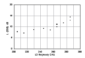
Fig. 8. SSB conversion loss (dB)
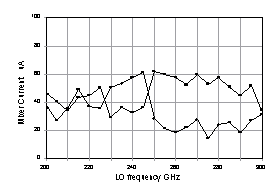
Fig. 9 DC currents in the component
mixers (µA).
DISCUSSION
The SSB receiver noise temperatures in Fig. 6 are, as expected,
approximately twice the DSB values obtained by a simple mixer similar
to one of the component mixers of the sideband separating mixer. With
some improvement in tuning it should be possible to obtain a flatter
noise temperature over the desired frequency band. The image rejection
is  9 dB, which is sufficient to remove image frequency atmospheric noise in radio astronomy applications, but is lower than expected. The variation of the image rejection with frequency suggests that LO leakage entering the signal port of the mixer may be spoiling the LO phasing at the component mixers. Because ~17 dB LO couplers are used, LO leakage to the signal port at the -20 dB level would appear at the individual mixers only ~3 dB below the desired LO and could account for the poor image rejection. We believe this LO leakage is through a mode under the quartz substrate, excited by the suspended stripline to CPW transition at the LO end of the substrate, and coupling into the similar transition at the signal end. To suppress such leakage, the present mixer contains a small piece of absorbing material. After the mixer measurements described here, it was realized that this absorber was too small and remote from the mixer substrate to have a significant effect. We are in the process of replacing it with a larger piece positioned closer to the substrate, and made of material with a higher attenuation constant [13].
An additional contribution to the poor image rejection arises from
the (image) termination on the input quadrature hybrid. Because of the
difficulty of achieving a given sheet resistance using AuPd, resistors
on the present wafer were 36% too high -- 68 ohms rather than 50 ohms. SIS mixers are seldom well matched to the LO, nor to signals in either sideband, and a mismatched termination on the hybrid can spoil the phasing of those waves at the two mixers through multiple reflections. Assuming identical component mixers with signal reflection coefficient  S, the effect of a mismatch
  H at the input hybrid is to produce an output at the IF image port corresponding to an image rejection |
 S
S H|2. Hence the present 68 ohm termination can contribute an image rejection no worse than 16 dB. LO power reflected at identical mixers, arriving at the mismatched termination, returns to the mixers with a phase
  MH, dependent on the electrical distance between mixer and termination, plus a
  /2 difference (between mixers) contributed by the quadrature hybrid.
  MH changes with LO frequency, causing the amplitude and phase of the LO at the mixers to vary. We expect the phase variation to have the more substantial effect on the image rejection. For the 68 ohm termination the maximum phase error between mixers is ~9°, corresponding to an image rejection of ~22 dB. We deduce that the high resistance of the termination on the quadrature hybrid is unlikely to account for more than about half the measured minimum image coupling.
The DC currents in the two mixers exhibit unexpected frequency dependence, as evident in Fig. 9. Above ~250 GHz, the currents differ by almost a factor of two. We do not yet know whether this is a characteristic only of the particular chip measured here, or whether it is caused by some error in the design.
An interesting and potentially useful property of this type of sideband separating mixer occurs when the mixer elements have anti-symmetrical I-V curves, as do SIS junctions. Then, reversing the polarity of the bias on one of the component mixers interchanges the sideband outputs. Hence a sideband separating mixer connected to a single IF channel can be used to receive signals in either sideband.
ACKNOWLEDGMENTS
The authors thank N. Horner, F. Johnson, and A. Marshall for fabricating and assembling the mixer, and K. Crady for his help in testing the mixer.
REFERENCES
*References marked with an asterisk (*) are available on the web at http://www.mma.nrao.edu/memos/ memolist.html
[*1] A. R. Thompson and A. R. Kerr, "Relative sensitivities of single and double sideband receivers for the MMA," Millimeter Array Memo. 168, National Radio Astronomy Observatory, Charlottesville VA, April 1997.
[*2] P. R. Jewell, J. G. Mangum, "System Temperatures, Single Versus Double Sideband Operation, and Optimum Receiver Performance," Millimeter Array Memo. 170, National Radio Astronomy Observatory, Charlottesville VA, April 1997.
[3] R. L. Akeson, J. E. Carlstrom, D. P. Woody, J. Kawamura, A. R. Kerr, S.-K. Pan, and K. Wan, "Development of a sideband separation receiver at 100 GHz," Proceedings of the Fourth International Symposium on Space Terahertz Technology, pp. 12-17, March 1993.
[4] C.-Y. E. Tong and R. Blundell, "A Quasi-Optical Image Separation Scheme for Millimeter and Submillimeter Waves," IEEE Trans. Microwave Theory Tech., vol. MTT-42, no. 11, pp. 2174-2177, Nov. 1994.
[5] A. R. Kerr and S.-K. Pan, "Design of planar image-separating and balanced SIS mixers," Proceedings of the Seventh International Symposium on Space Terahertz Technology, pp. 207-219, 12-14 March 1996.
[6] A. R. Kerr, S.-K. Pan, A. W. Lichtenberger and H. H. Huang, "A Tunerless SIS mixer for 200–280 GHz with low output capacitance and inductance," Proceedings of the Ninth International Symposium on Space Terahertz Technology, 17-19 March 1998.
[7] R. L. Sandstrom, A. W. Kleinsasser, W. J. Gallagher, and S. I. Raider, "Josephson Integrated Circuit Process for Scientific Applications," IEEE Transactions on Magnetics, vol. MAG-23, no. 2, pp. 1484-1488, March 1987.
[8] Hercules HR500-2S film is 0.00075" thick. It consists of 0.0005" biaxially oriented polypropylene coated both sides with polyvinylidene chloride. The plastic film division of Hercules is now operated by Applied Extrusion Technology Inc., Covington, VA. HR500-2S is now obsolete and has been superceded by a similar material called UBS-2.
[9] Gore RA-7957 expanded PTFE has a submicroscopic open-cell structure. It has a density 25% of that of solid PTFE.
[10] S.-K. Pan, A. R. Kerr, M. J. Feldman, A. Kleinsasser, J. Stasiak, R. L. Sandstrom and W. J. Gallagher, "A 85-116 GHz SIS receiver using inductively shunted edge-junctions," IEEE Trans. Microwave Theory Tech., vol. MTT-37, no. 3, pp. 580-592, March 1989.
![]() 9 dB, which we hope to improve by reducing leakage of LO power under the substrate into the signal port, and by improving the match of the cold termination of the fourth port of the input quadrature hybrid.
9 dB, which we hope to improve by reducing leakage of LO power under the substrate into the signal port, and by improving the match of the cold termination of the fourth port of the input quadrature hybrid.

 Fig. 3. A length of capacitively loaded coplanar waveguide (CLCPW). Dimensions are in microns.
 RNCJ = 4 at 250 GHz. To
allow for uncertainties and variation in the processing, twelve
designs were included on the masks --
three tuning stub lengths and four series capacitor widths.


 S, the effect of a mismatch
  MH, dependent on the electrical distance between mixer and termination, plus a
  /2 difference (between mixers) contributed by the quadrature hybrid.